Safety valves: principle of operation and characteristics
Device and principle of operation of valves
The main elements valve limiter are a spark gap and a non-linear resistor, which are connected in series between the live wire and the ground in parallel with the protected insulation.
When a lightning surge impulse is applied to the arrester, its spark gap is broken and current flows through the arrester. Thus, the retainer is put into operation. The voltage at which the spark gaps break is called the breakdown voltage of the arrester.
After the breakdown of the spark gap, the voltage in the spark gap, and hence on the insulation it protects, decreases to a value equal to the product of the impulse current Azi on resistor resistance in series R and. This voltage is called residual voltage Ubasn. Its value does not remain constant, but changes along with a change in the magnitude of the impulse current as it passes through the spark gap.However, during the entire time of operation of the arrester, the residual voltage must not rise to a value dangerous to the protected insulation.
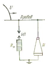
Rice. 1. Electric circuit diagram turning on valves. IP — spark, Rn — non-linear resistor resistance, U — lightning overvoltage impulse, And — insulation of the protected object.
After the impulse current stops flowing through the arrester, the current due to the frequency voltage continues to flow. This current is called the accompanying current. The spark gaps of the arrester must ensure reliable extinguishing of the next arc when it first crosses zero.
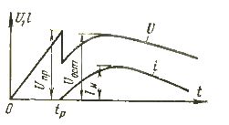
Rice. 2. The shape of the voltage pulse before and after actuation of the valve. Tp is the reaction time of the spark gap (discharge time), Azi is the impulse current of the discharger.
Valve supply voltage
The reliability of extinguishing the arc from the spark gap depends on the value of the voltage of the frequency of the supply of the arrester at the moment of extinguishing the subsequent current. The maximum value of the voltage at which the spark gaps of the limiters reliably interrupt the accompanying current is called the maximum allowable voltage or damping voltage Ugash.
The magnitude of the cooling voltage of the valve limiter is determined by the operating mode of the electrical installation in which it operates. Since during thunderstorms there may be a simultaneous short-circuit of one phase to ground and operation of valve limiters on other undamaged phases, the voltage in these phases rises in this case. The quenching voltage of the valves is selected taking into account such voltage increases.
For limiters operating in networks with an isolated neutral, the extinguishing voltage is assumed to be Uburning = 1.1 x 1.73 x Uf = 1.1 Un, where Uf — voltage of the working phase.
This takes into account the possibility of increasing the voltage of the undamaged phases to linear when one phase is shorted to ground and by another 10% due to the user's voltage regulation. Therefore, the highest operating voltage of the arrester is 110% of the rated voltage of the Unom network.
For arresters operating in networks with a solid earthed neutral, the quench voltage is 1.4 Uf, t.d. 0.8 of the nominal network voltage: Ubreakdown = 1.4 Uf = 0.8 UNo. Therefore, such arresters are sometimes called 80%.
Spark gaps in the valves
Valve spark gaps must meet the following requirements: have a stable breakdown voltage with minimal spread, have a flat volt-second characteristic, not change its breakdown voltage after repeated operations, extinguish the arc of the aftercurrent when it first passes through zero. These requirements are met by multiple spark gaps that are assembled from single spark gaps with small air gaps. Single candles are connected in series and for each of them at the highest allowable voltage there is about 2 kV.
Splitting the arc into short arcs into single spark gaps increases the arc suppression properties of the valve arrester, which is explained by the intense cooling of the arc and the large voltage drop at each electrode (cathode voltage drop effect).
The breakdown voltage of the spark gaps in a valve discharger when exposed to atmospheric overvoltage is determined by its volt-second characteristic, i.e. the dependence of the discharge time on the amplitude of the overvoltage pulse. Discharge time is the time from the start of the surge pulse to the breakdown of the spark gap of the arrester.
For effective insulation protection, its volt-second characteristic must lie higher than the volt-second characteristic of the arrester. The displacement of the volt-second characteristics is necessary to preserve the reliability of the protection in case of accidental weakening of the insulation during operation, as well as due to the presence of areas of propagation of discharge voltages both in the arrester itself and in the protected insulation.
The volt-second characteristic of the protector should have a flat shape. If it is steep, as shown in fig. 3 with a dotted line, this will lead to the fact that the arrester will lose its universality, since each type of equipment with an individual volt-second characteristic will require its own special limiter.
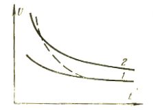
Rice. 3. Volt-second characteristics of valve limiters and the insulation protected by them.
A non-linear resistor. Two opposite requirements are imposed on it: the moment the lightning current passes through it, its resistance must decrease; when the accompanying frequency power current passes through it, it must, on the contrary, increase.These requirements are met resistance of carborundum, which changes depending on the voltage applied to it: the higher the applied voltage, the lower its resistance and, conversely, the lower the applied voltage, the greater is its resistance.
In addition, the series-connected resistance of the carburund, as an active resistance, reduces the phase shift between the accompanying current and voltage, and with their simultaneous passage through the zero value, the extinguishing of the arc is facilitated.
As the voltage increases, the value of the resistance of the barrier layers decreases, which ensures the passage of large currents with relatively small voltage drops.
HTML clipboard The dependence of the voltage across the spark gap on the value of the current passing through it (current-voltage characteristic) is approximately expressed by the equation:
U = CAα,
where U is the voltage across the resistance of the non-linear resistor valve protector, I — the current passing through the non-linear resistor, C is a constant numerically equal to the resistance at a current of 1 A, α The ventilation factor is.
The smaller the coefficient α, the less the voltage of the non-linear resistor changes when the current passing through it changes, and the less the remaining voltage of the valve.
The residual voltage values given in the valve limiter certificate are given for the normalized impulse currents. The values of these currents are in the range of 3,000-10,000 A.
Each current pulse leaves a trace of destruction in the series resistor — a breakdown of the barrier layer of individual carborundum grains occurs.Repeated passage of current pulses leads to complete failure of the resistor and destruction of the arrester. Complete failure of the resistor occurs the earlier, the greater the amplitude and length of the current pulse. Therefore, the flow capacity of the valve restrictor is limited. When evaluating the throughput of valve restrictors, the throughput of both series resistors and spark gaps is taken into account.
The resistors must withstand without damage 20 current pulses of duration 20/40 µs with amplitude depending on the type of limiter. For example, for arresters of the RVP and RVO type with a voltage of 3 — 35 kV, the current amplitude is 5000 A, for the RVS type with a voltage of 16 — 220 kV — 10,000 A, and RVM and RVMG with a voltage of 3 — 500 kV — 10,000 A.
To increase the protective properties of the valve spark gap, it is necessary to reduce the residual voltage, which can be achieved by reducing the valve coefficient α of the series non-linear resistor, while increasing the arc suppression properties of the spark gaps.
Increasing the arc suppression properties of the spark gaps makes it possible to increase the shunt current interrupted by them, and therefore makes it possible to reduce the resistance of the series resistor. At present, the technical improvement of the valves is carried out along these lines.
it should be noted that in the valve limiter circuit the grounding device is of great importance. In the absence of grounding, the arrester cannot operate.
The earthing of the valve limiter and the equipment protected by it are combined.In cases where the valve limiter is for some reason separated from the protected equipment grounding, its value is normalized depending on the isolation level of the equipment.
Installation of restraints
After a thorough inspection, the stops are installed on the supporting structures, checked for level and plumb with padding, if necessary, under the base of the sheet metal sections and fixed on the supports using a bolted clamp.