SF6 circuit breakers 110 kV and above
 High-voltage circuit breakers, in which SF6 is used as insulating and arcing media, are becoming more widespread because they have high switching rates and mechanical resources, breaking capacity, compactness, and reliability compared to air, oil, and low-oil high voltage circuit breakers.
The success in the development of SF6 circuit breakers directly had a significant impact on the commissioning of compact outdoor switchgear, indoor switchgear and SF6 gas-insulated switchgear. SF6 circuit breakers use different arc extinguishing methods depending on the rated voltage, rated breaking current and characteristics of the power system (or individual electrical installation).
In gas-insulated arc extinguishing devices, unlike air arc extinguishing devices, when the arc is extinguished, the outflow of gas through the nozzle does not take place into the atmosphere, but into the closed volume of the chamber filled with SF6 gas at a relatively small excess pressure .
According to the method of extinguishing the electric arc during tripping, the following SF6 circuit breakers are distinguished:
1. SF6 automatic compression switch, where the required flow rate of SF6 gas through the nozzles of the compression arc extinguishing device is created by the moving system of the switch (single pressure stage automatic compression switch).
2. SF6 circuit breaker with electromagnetic blowout, in which the extinguishing of the arc in the arc device is ensured by its rotation along the ring contacts under the action of the magnetic field created by the current to be extinguished.
3. SF6 circuit breaker with high and low pressure chambers, in which the principle of providing a burst of gas through the nozzles in the arc extinguishing device is similar to air arc extinguishing devices (SF6 switch with two pressure stages).
4. SF6 self-generating circuit breaker, in which the required mass flow rate of SF6 gas through the nozzles of the arc extinguishing device is created by heating and increasing the pressure of SF6 gas through the tripping arc in a special chamber (SF6 self-generating circuit breaker with one stage of pressure).

Let's look at some typical SF6 circuit breaker designs for 110 kV and above.
Circuit breakers SF6 110 kV and higher for a single break of various companies have the following nominal parameters: Unom = 110-330 kV, Inom = 1-8 kA, Io.nom = 25-63 kA, SF6 gas pressure = 0.45 -0.7 MPa (abs), trip time 2-3 periods of short circuit current.Intensive research and testing of domestic and foreign companies made it possible to develop and put into operation a SF6 circuit breaker with a single break at Unom = 330-550 kV at Io.nom = 40-50 kA and a current tripping time of one current period at short circuit.
A typical SF6 circuit breaker design is shown in Fig. 1.
The device is in the off position and pins 5 and 3 are open.
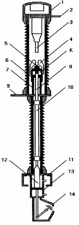
Rice. 1.
Current is supplied to the fixed contact 3 through flange 2, and to the movable contact 5 through flange 9. A chamber with an adsorbent is installed in the upper cover 1. The load-bearing insulation structure of the SF6 circuit breaker is fixed on the foot pad 11. When the switch is turned on, a pneumatic actuator 13 is activated, the rod 12 of which is connected by an insulating rod 10 and a steel rod 8 with a movable one. contact 5. The latter is firmly connected to a fluoroplastic nozzle 4 and a movable cylinder 6. The entire movable system of the EV (elements 12-10-8-6-5) moves upward relative to the stationary piston 7 and the cavity K of the arc extinguishing system of the switch increases.
When the switch is off, the rod 12 of the actuating mechanism pulls the movable system down and an increased pressure is created in the cavity K compared to the pressure in the switch chamber. Such auto-compression of SF6 gas ensures the outflow of the gas medium through the nozzle, intense cooling of the electric arc that occurs between contacts 3 and 5 during shutdown. Position indicator 14 gives possibility of visual control the starting position of the contact system of the switch.In a number of designs of SF6 autocompression circuit breakers, springs, hydraulic actuators are used, and the flow of SF6 gas through nozzles into the arc chute is carried out according to the principle of two-way blowing.
In fig. 2 shows a 220 kV tank circuit breaker with gas insulation type VGBU (Inom = 2500 A, Io.nom = 40 kA NIIVA OJSC with autonomous hydraulic drive 5 and built-in current transformers 2. EV has three-phase control (one drive for three phases) and is equipped with porcelain (polymer) covers for 1 air-SF6 bushings.
In the gas-filled tank 3, there is an arc extinguishing device, which is connected to the hydraulic drive 5 through a transmission mechanism located in the gas-filled chamber 4. The switch structure of the gas tank is fixed on a metal frame 6. To fill the circuit breaker with SF6 coupling 7 is used. is equal to one atm (abs.) and then it is necessary to ensure p = pnom.

Rice. 2.
The advantages of gas-insulated tank circuit breakers with built-in current transformers over «core gas-insulated circuit breaker plus stand-alone current transformer» kits are: increased seismic resistance, smaller substation distribution area, less required major works on time of construction of substations, increased safety of substation personnel (arc extinguishing devices are located in grounded metal tanks), the possibility of using SF6 heating gas when used in cold climate regions.
When designing 220 kV and higher tank circuit breakers for outdoor switchgear, it is necessary to increase the nominal pressure of SF6 gas (pH> 4.5 atm (abs.)). Therefore, heating of the gas medium is introduced to prevent SF6 gas is used from liquefaction at low ambient temperatures or mixtures of SF6 gas with nitrogen or tetrafluoromethane.
As practice shows, for a rated voltage of 330-500 kV, single-break tank circuit breakers for rated currents of 40-63 kA are the most promising type of switching equipment for switchgear and outdoor switchgear.
The circuit breaker VGB-750-50 / 4000 U1 developed by JSC NIIVA (Fig. 3) with a two-displacement autocompression device for arc extinguishing, built-in current transformers, polymer air bushings SF6, is equipped with two hydraulic drives per pole, which allows a total trip time not more than duration of two periods of current at supply frequency.
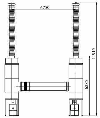
Rice. 3.
In fig. 4 shows a section of a single-pole VGB-750-50 / 4000U1 arc suppressor with upstream resistors (to limit switching surges). The movable contact of these resistors is mechanically connected to the movable circuit breaker system.
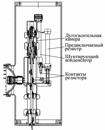
Rice. 4
In the closed position of the SF6 circuit breaker, the resistors are bridged by the main contacts. When switching off, the resistor contacts open first, then the main contacts, then the arcing contacts. When switching on, the resistor contacts close first, followed by the arc and main contacts. To equalize the voltage distribution, each break is connected with capacitors.
The distribution is obtained from SF6 type single-break column circuit breakers for rated voltage 110-220 kV with rated breaking current 40-50 kA.
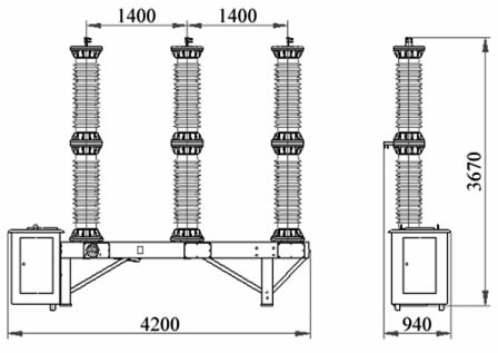
Rice. 5
A typical design of a VGP 110 kV gas-insulated wire circuit breaker (Inom = 2500 A, Io.nom = 40 kA) with a spring drive of Electroapparat OJSC is shown in fig. 5.
See also on this topic: Comparative characteristics of oil, vacuum and SF6 circuit breakers for high voltage