Bus systems for distribution and transformer substations
For the transmission and distribution of electrical energy, overhead lines or power cables with different voltage levels are used, and their selection is based on an analysis of technical and economic aspects.
To ensure high power supply reliability, electrical networks can be more or less multi-chain. This allows, in the event of failure of individual transmission lines, to continue supplying consumers through other lines.
The points on networks where two or more lines converge are called nodal points. Switching devices designed to disconnect individual line circuits in the event of breakdowns or maintenance and repair are always installed at these junction points.
All switching devices necessary for this, as well as measuring, control, protection and auxiliary equipment are located in a distribution substation.
If, in addition to these devices, transformers are installed in the distribution substation to change the level nevertheless, such a substation is called substation.
Distribution substations are equipped with the following main structural elements:
- Shina;
- Disconnector;
- Power switch;
- current and voltage converters;
- Surge limiter;
- Earthing switch;
- Possibly: transformer.
Substations are equipped with assemblies and components with technical characteristics that meet the requirements and possible mechanical and electrical loads.
Since modern substations are mainly controlled remotely, they are equipped with additional monitoring and control devices. In addition, substations are equipped with metering and measuring devices for electricity supplied to consumers, as well as surge protection devices.
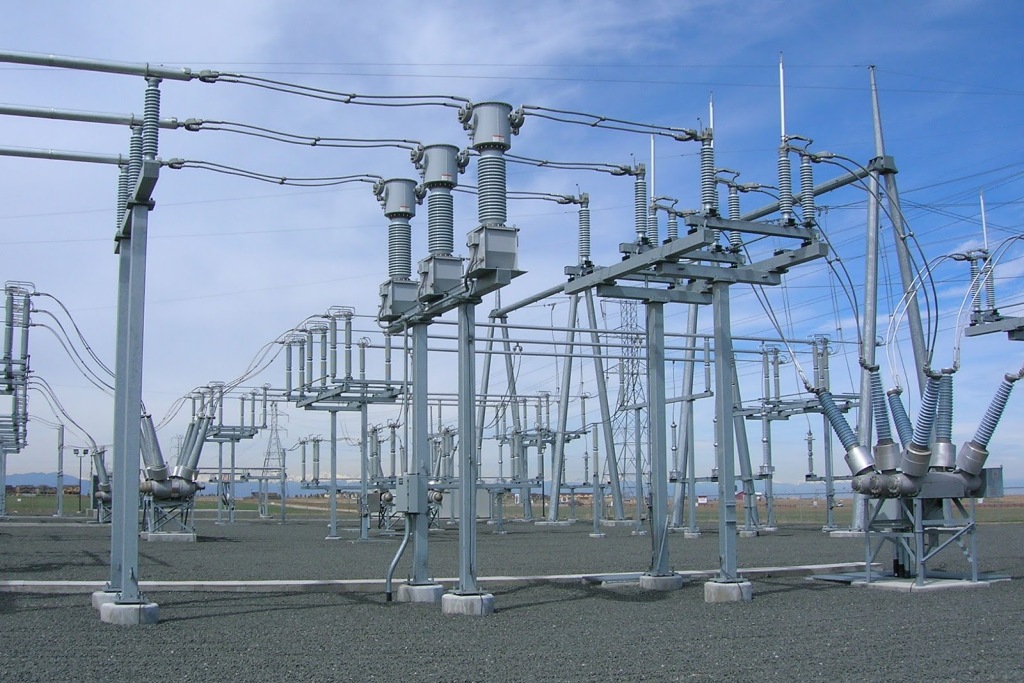
The main element of the distribution substation is the busbar. As a rule, it looks like a short air line. For very high currents, it is laid in an internally oil-cooled tube.
There are several types of bus arrangements and the choice of a particular arrangement depends on various factors such as system voltage, substation position in the system, power supply reliability, flexibility and cost.
From a physical point of view, the bus is the node of the network. At this point separate lines begin and end, which in this context are called feeders.
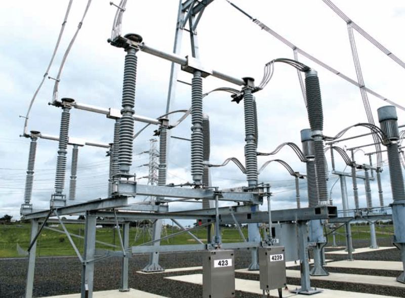
Feeders can be turned on and off using switches. Since these switches carry operating current and, in case of malfunction, emergency current, they are called power switches.
Modern high voltage power switches level up to 380 kV are able to reliably and without damage switch on / off currents up to 80 kA. Power switches require regular maintenance.
To ensure the safety of such work, the circuit breakers are equipped with the so-called disconnectors… Unlike power switches, disconnectors can only be turned on / off in the off state, ie. only after opening the corresponding circuit breakers.
To avoid erroneous switching operations, disconnectors and circuit breakers are mutually interlocked mechanically.
In addition, the disconnectors are designed to create a visible trip point, since in power switches this point is located in the arc chute and is hidden from view. According to safety rules, when disconnecting sections of power lines, the disconnection point must be visible.
In order to carry out maintenance activities on the busbars without interrupting the power supply, the distribution substation must be equipped with at least two parallel busbars.
To increase the flexibility of the network, it is possible to connect individual feeders to the busbars using disconnectors. In addition, to increase the freedom of action, the rail can be divided into several sections (the so-called Longitudinal section of the rail).
Thanks to these measures, a large electrical network can be divided into several sections with galvanic isolation, which limits the amount of currents in the event of a possible short circuit.
The described actions are usually called corrective switching operations, and the optimal network configuration is determined in advance using load distribution and short-circuit protection programs.
By optimizing these operations, the full potential of the power grid can be used without creating hazardous working conditions.
Distribution and transformer substations are divided into separate panels that perform specific functions. There are power panels, outlet power panels, and connection panels.
The design of the individual panels is usually unified. In electrical diagrams, panels are always shown in unipolar form. This means that in diagrams of this type, using standard symbols, only the devices necessary for the operation of the installation are depicted.

Schematic diagram of the power supply
According to the scheme shown in the figure, both power panels and panels with outgoing power devices are built. Both disconnectors are designed to trip the breaker together with current and voltage measuring transformers.
If the installation consists of several buses, the number of bus disconnectors must be increased by the corresponding number of times for two buses.
Instrument transformers record the relevant parameters required for operation, counting and protection devices.
A grounding switch is used to protect the line from inductive and capacitive effects of adjacent lines during maintenance, as well as to protect against lightning strikes. Because of its function, the earthing switch is sometimes called a service earthing switch.
To disconnect larger sections of the network in the event of an emergency or to carry out necessary maintenance work, at least two parallel buses are usually used.

Double rail system
Using the connection plate power switch, both buses can be connected to a single node point. This type of connection is called a cross connection. Thanks to the cross connection, the busbars can be changed without interrupting the power supply.
Power panels and panels with outgoing power devices, if necessary, can be connected to different buses, as a result of which the power supply is not interrupted.
Since the disconnectors can only be switched on/off in the off state, the power switch must be integrated into the connection of the two buses. If the busbars are interconnected, then first you need to close both disconnectors and only then the power switch.
When connecting the busbars, appropriate action must be taken (for example, switching the tap-changers of the transformers) to equalize their potentials, otherwise high transient currents will appear in the busbars when connecting the busbars.
After connecting the busbars, any connection and disconnection of the power supplies can be done because there is no longer any potential difference in the busbars.
It is only necessary to ensure that the other disconnector on the same feeder closes before opening one disconnector. Otherwise, the disconnector will be under load when opened, which can cause destruction and even damage to other components of the installation.The disconnectors are therefore protected against accidental opening by means of special locking devices (electrical and pneumatic).
To study the basic processes taking place in a distribution substation, you can assemble an experimental circuit with which you can perform basic switching operations.
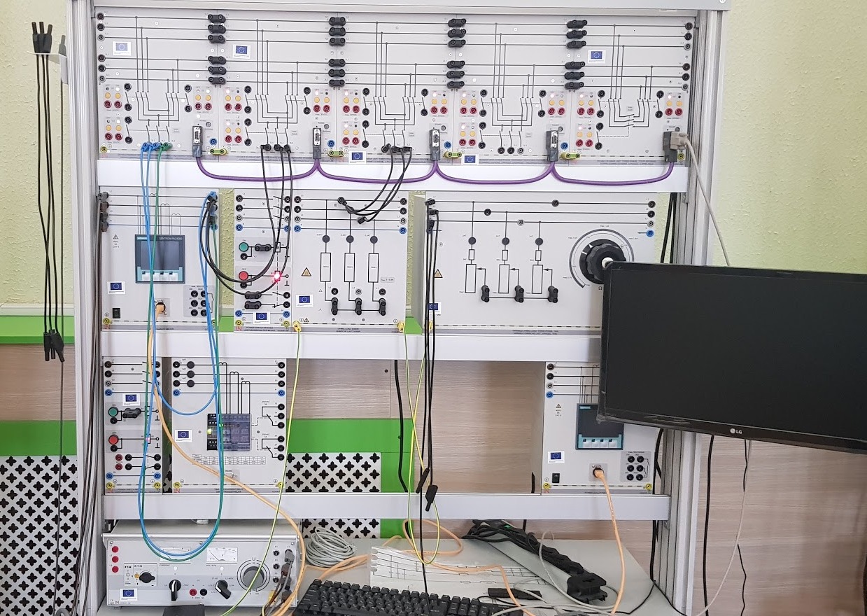
Experimental stand
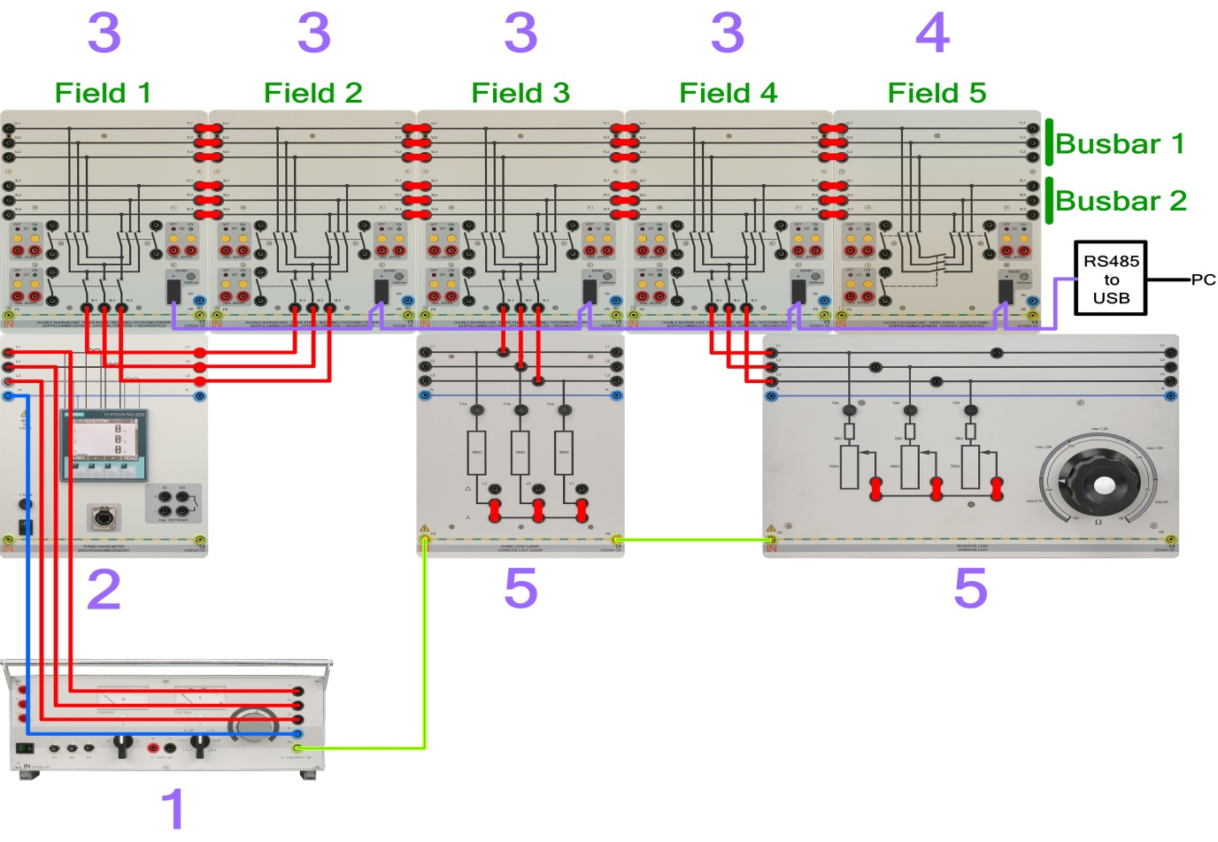
Schematic diagram of the experimental stand
Such an experimental stand for the study of bus systems of distribution and transformer substations (laboratory stand of the German company Lucas-Nuelle) is in the resource center "Econtechnopark Volma".
For a description of the Resource Center's learning lab equipment, see here — and here —
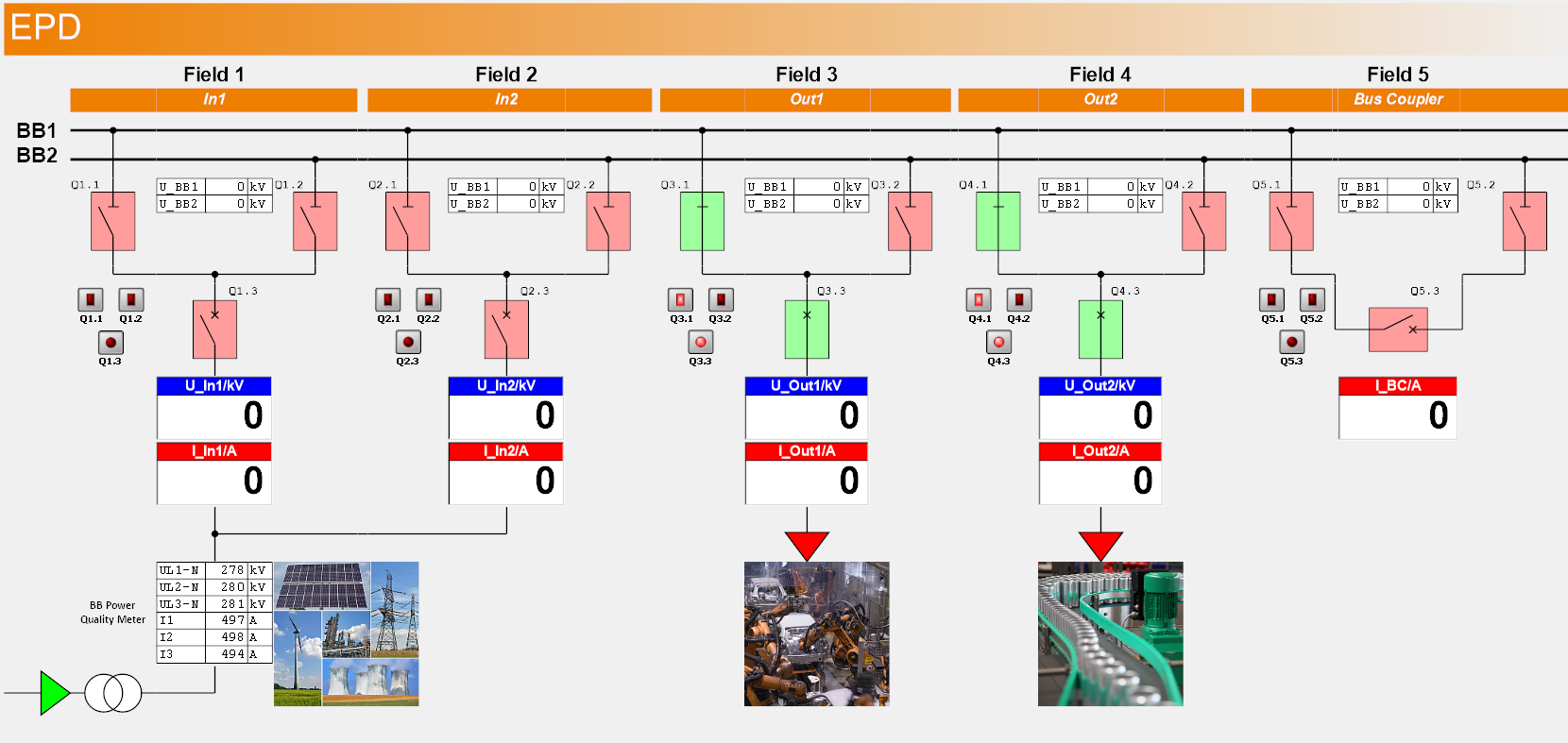
SCADA screenshot for power Lab: dual bus
The analysis of the voltage and current parameters is performed using the SCADA for power Lab (SO4001-3F) software. To get the most out of a dual bus system, it is recommended that each bus be connected to its own voltage source.