Oil switch VMG-10
 Oil circuit breaker type VMG-10 refers to small volume (pot) oil circuit breakers and is a switching device capable of breaking any load and short circuit currents up to the limit breaking current of 20 kA. The VMG-10 circuit breaker is widely used in transformer substations RU-6-10 kV 110-35 kV.
The principle of operation of the VMG-10 circuit breaker is based on extinguishing the electric arc, which occurs when the contacts are opened by the flow of a gas-oil mixture, which is formed as a result of the intensive decomposition of transformer oil under the action of high arc burning temperature. This flow receives a certain direction in a special arc extinguishing chamber located in the arc burning zone.
The VMG-10 type oil switches can be operated by a PE-11 direct current electromagnetic actuator or a PP-67 spring actuator.
Oil breaker device VMG-10
Three poles of the switch are mounted on a common welded frame (Fig. 1).On the front side of the frame there are six porcelain support insulators 10 with internal elastic mechanical fastening. On each pair of insulators, a pole of switch 1 is suspended.
The switch control mechanism consists of a shaft 3 with two levers 4, 13 welded to it and three pairs of levers. A buffer spring is attached to the small arms of these levers located at the middle pole. The large arms of the levers 2, made of insulating material, are connected to the current-carrying contact rods 5 by means of clamps 11. They serve to transfer movement from the switch shaft to the contact rod.
A two-arm lever 12 (with rollers at the ends) welded to the breaker shaft between the side and center poles limits the on and off position of the gel breaker. When turned on, one of the rollers reaches the stop bolt 6, when it is turned off, the other roller moves the stem of the oil buffer 7. To connect the switch to the drive, a special lever 4 or 13 is installed on the shaft …….
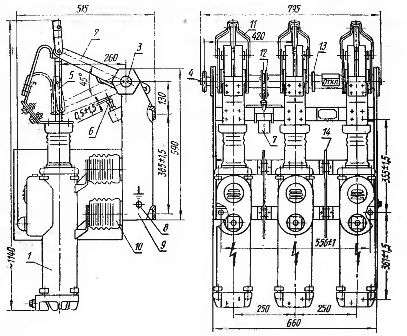
Rice. 1. The VMG-10 oil switch device (1 — switch pole, 2 — insulating lever, 3 — shaft, 4, 13 — levers, 5 — contact rod, 6 — locking bolt, 7 — oil buffer, 8 — grounding bolt , 9 — frame, 10 — insulator, 11 — clamp, 12 — lever with rollers, 14 — insulating barrier.)
The main part of the VMG-10 breaker pole is cylinder 1 (Fig. 2). For circuit-breakers for rated current 1000 A, the cylinders are made of brass, for rated current 630 A — of steel with a longitudinal non-magnetic seam. Two clamps 7 are welded to each cylinder to secure it to the insulator and housing 2 with oil filler plug 5 and oil indicator 3.The casing serves as an additional expansion volume, inside which a centrifugal oil separator 13 is located. The gases formed when the currents are turned off leave the breaker pole through special covers 4 located on the casing.
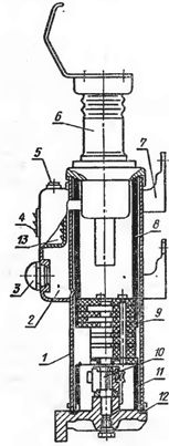
Rice. 2. Pole of the oil switch VMG -10 (1 — welded cylinder, 2 — housing, 3 — oil indicator, 4 — louvers, 5 — oil filler plug, 6 — insulator, 7 — bracket, 8, 11 — insulating cylinders, 9 — arc chute, 10 — internal contact, 12 — seal, 13 — oil separator)
The insulating cylinders 8 and 11 are placed inside the main cylinder, between which an arc-shaped chamber 9 is installed. The insulation between the switch cylinders, if necessary, can be reinforced with special partitions 14 (Fig. 1).
The movable contact rod is isolated from the cylinder, which is electrically connected to the fixed socket contact 10 (Fig. 2) by a porcelain sleeve 6 fixed in the upper part of the cylinder. A contact rod seal is placed at the top of the insulator to prevent gases and oil escaping from the cylinder when it is shut down. Attached to the insulator cap is a current-carrying clip that serves as the upper terminal of the gel switch.
A transverse oil blast circuit breaker consists of a pack of insulating plates held together by rattling insulating pins. In the lower part of the chamber there are transverse blowing channels one above the other, and in the upper part there are «pockets» of oil. In the transverse air ducts, conclusions are made upwards. Large and medium currents are quenched by blowing in the cross channels, and small currents, if not quenched in the channels, are quenched by blowing in oil "pockets".
The distance between the lower surface of the arc chute and the socket contact (3 — 5 mm) is of great importance for normal gas generation and arc extinguishing. In the braking process, from the moment the arc starts to the moment the contact rod opens the lower drop of the transverse burst due to the decomposition of the oil under the arc chute, the pressure in the lower part of the cylinder increases (up to 10 MPa). If the gap between the stationary contact and the chamber increases, then the cylinder can burst, and if it decreases, then insufficient gas formation occurs, which leads to a delay in arc extinguishing.
In the lower part, the cylinder is closed with a movable cover, on which there is a fixed socket contact 10. A rubber control is installed between the cover and the cylinder. In the upper part of the movable contact rod there is a fixed contact block, to the end of which flexible wires are attached. To reduce burning of the movable contact when extinguishing the arc, a metal-ceramic tip is attached to the lower part of the rod.
The full stroke of the contact rod should be 210 ± 5 mm, the stroke in the contacts should be 45 ± 5 mm, and the contact time difference between the contacts along the stroke should not be more than 5 mm.
When the switch is turned on, the distance between the lower plane of the contact rod column and the pa bolt head and the sleeve cap should be 25 — 30 mm, and the gap between the roller and the stop bolt should be 0.5 — 1.5 mm.
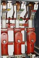
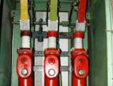
Rice. 3. General view of the oil breaker VMG-10
The room intended for installation of the VMG-10 oil circuit breaker must be closed, explosion-proof and fireproof, free of dust and chemically active environment and protected from direct penetration of atmospheric precipitation.
The designation structure of the VMG-10 oil circuit breaker:
Example: switch VMG -10-20 / 630, VMG -10 / 20-1000 — V — switch, M — oil, G — pot type, 10 — rated voltage, kV, 20 — rated breaking current, kA, 630; 1000 — nominal current, A.