Automatic control in load function
 In many cases it is necessary to control the forces and moments acting on certain parts of the machine. Mechanisms for which this type of control is required primarily include various clamping devices, for example, electric wrenches, electric wrenches, electric chucks, column clamping mechanisms for radial drilling machines, cross bars for planers and large drilling machines, etc.
One of the simplest methods of force control is based on the use of some element that is displaced by the applied force, compressing the spring and acting on the travel switch. An approximate kinematic diagram of one of the electric cassettes with such a device is shown in fig. 1.
The electric motor 6 rotates the worm 7, which drives the worm wheel 3. A cam clutch 4 is connected to the wheel 3, the second half of which sits on a sliding key on the shaft 8. When the electromagnet 5 is turned on, the clutch 4 turns on and the shaft 8 begins to rotate. rotates.In this case, the cam coupling 9, which is in the on state, also rotates, which transmits the rotation to the nut 10. The latter imparts a translational movement to the rod 11. This causes, depending on the direction of rotation of the electric motor 6, the convergence or divergence of the cams 12.
When the parts are compressed by the cams, the motor 6 transmits to the nut 10 an increasing torque. The clutch 9 has beveled cams, and when the moment transmitted by it reaches a certain value, the movable half of the clutch, pressing the spring 2, will be pushed to the left. In this case, the movement switch 1 will be triggered, which will cause the electric motor 6 to be disconnected from the network. The clamping force of the workpiece is determined by the precompression value of the spring 2.
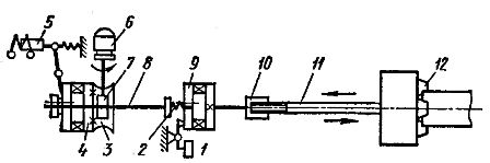
Rice. 1. Schematic of the electric cassette
In the considered clamping devices, as the clamping force increases, the moment of resistance on the motor shaft increases and, accordingly, the current consumed by it. Therefore, force control in clamping devices can also be based on the use of a current relay, the coil of which is connected in series to the circuit of the current consumed by the motor. Clamping stops as soon as the current reaches a value corresponding to the setting of the current relay and the required clamping force.
On automatic lines, an electric switch is used, in which the movement from the electric motor to the spindle is transmitted through a kinematic chain with a single-tooth clutch, so that the spindle immediately begins to rotate at full frequency. When the «clamp» button is pressed, the contactor of the clamp is activated and the motor starts to rotate.
An overcurrent relay whose coil is connected to the main circuit is tripped and its NC contact opens. However, this opening has no effect on the circuit, because during the short-term process of starting the electric motor, the button is pressed. When starting is complete, the motor current decreases, the PT relay closes its contact, and the short circuit contactor switches to self-energization through the short circuit closing contact and the PT opening contact. As the clamping force increases, the motor current increases and when the clamping force reaches the required value, the PT relay is energized and stops the motor.
When you press the button O («Spin»), the motor turns on to rotate in the opposite direction. In this case, the clutch with one tooth engages the driven part of the kinematic chain with a pressure that overcomes, due to the kinetic energy of the moving parts of the electric drive, the frictional force that increased during the stop of the kinematic chain. However, the clamping devices constructed according to such a scheme do not provide a stable clamping force, as well as regulation of this force within the necessary limits.
The key does not have these disadvantages (Fig. 3). An asynchronous squirrel-cage motor 1 through an electromagnetic clutch 2 and a gearbox 3 rotates the torsion bar 4, which then transmits the movement to the key nozzle 9. The torsion bar is a package of steel plates. As the transmitted torque increases, the torsion bar twists. In this case, there is a rotation of the steel rings 5 and 6 of the induction primary torque converter, firmly connected to the ends of the torsion bar 4.Rings 5 and 6 are provided with end teeth facing each other.
When the torsion bar is twisted, the opposing teeth of the rings are displaced relative to each other. This leads to a change in the inductance of the coil 8 of the torque converter built into the magnetic circuit 7. With a certain change in the inductance of the coil, the converter sends a signal to turn off the electromagnetic clutch 2.
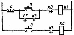
Rice. 2. Clamping device control circuit
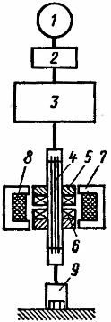
Rice. 3. Diagram of a wrench
The blanks are processed by removing chips from different sections. Therefore, different forces arise in the AIDS system, and the elements of this system receive different elastic deformations, which leads to additional processing errors. Elastic deformations of the elements of the AIDS system can be measured and compensated by automatic movements in the opposite direction. This leads to an increase in the accuracy of part production. Automatic compensation of elastic deformations of the elements of the AIDS system is called automatic control of elastic displacements or non-strict adaptive control.
Automatic compensation of elastic displacements of the AIDS system is developing rapidly. In addition to increasing the accuracy of processing, such control in many cases provides an increase in labor productivity (2-6 times) and provides high economic efficiency. This is due to the ability to process many parts in one pass. In addition, automatic elastic compensation prevents tool breakage.
The size AΔ of the processed part is summed algebraically or vectorially from the size Ау of the setting, the size АС of the static setting and the size Аd of the dynamic setting:

The dimension Ac is the distance between the cutting edges of the tool and the bases of the machine, set in the absence of cutting. The size of Ada is determined depending on the selected treatment regimens and the severity of the AIDS system. To ensure the consistency of the size AΔ of a batch of parts, it is possible to compensate for the deviation ΔAd of the size of the dynamic setting by making a correction ΔA'c = — ΔAd to the size Ac of the static setting. It is also possible to automatically compensate for deviations ΔAd of the dynamic setting size by making the correction ΔA’d = — ΔAd. In some cases, both control methods are used together.
To control elastic movements, elastic links are used, specially embedded in dimensional chains, the deformation of which is perceived by special electrical transducers. In the considered systems, inductive converters are most widely used. The closer the transducer is to the cutting tool or workpiece, the faster the automatic control system will be.
In some cases, it is possible to measure not deviations, but the force that causes them, having previously determined the relationship between these factors. this moment by measuring the current consumed by the motor. However, removing the control point from the cutting area reduces the accuracy and speed of the automatic control system.
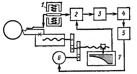
Fig.4. Schematic of adaptive turn control
In the circuit for controlling the size of the static adjustment during rotation (Fig. 4), the elastic deformation (squeezing) of the cutter is perceived by the converter 1, the voltage of which is transmitted to the comparator 2 and then through the amplifier 3 to the comparator 4, which also receives the control signal. The device 4, through the amplifier 5, supplies voltage to the transverse feed motor 6, which moves the tool in the direction of the workpiece.
At the same time, the slider of the potentiometer 7 moves, which controls the movement of the support carrier. The voltage of the potentiometer 7 is fed to the comparator 2. When the movement completely compensates for the deviation of the cutter, the voltage at the output of the comparator 2 disappears. In this case, the power supply to motor 6 is interrupted. Using a profile potentiometer or moving its slider by means of a cam, it is possible to change the functional relationship between the release of the cutter and its movement.
The scheme for controlling the size of the dynamic adjustment of the vertical cutter is shown in Fig. 5. In this machine, driver 1 supplies comparator 2 with a voltage that determines the amount of feed. The amount of stress is determined by the selected processing size according to a calibration curve relating the cutting force and stiffness of the AIDS system to the size of the dynamic setting. In addition, through the amplifier 3, this voltage is supplied to the electric motor 4 of the table power supply.
The motor moves the table using a lead screw. In this case, the lead screw nut, elastically displaced under the influence of the shear force component, bends the flat spring.The deformation of this spring is perceived by the converter 5, the voltage of which is transmitted through the amplifier 6 to the comparator 2, changing the power supply so that the size of the dynamic adjustment remains constant. Depending on the magnitude and sign of the voltage discrepancy supplied through the amplifier 3 to the adjustable electric motor 4, there is a change in the power supply in one direction or another.
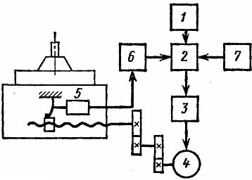
Rice. 5. Scheme of adaptive control during milling
The approach of the workpiece to the tool is carried out at the highest speed. To prevent tool breakage, the amount of feed applied is set in the form of a corresponding additional voltage input to comparator 2 of block 7.
To keep the size of the dynamic setting, you can also adjust the stiffness of the AIDS system so that as the cutting force increases, the stiffness increases and decreases as it decreases. For such adjustment, a special connection with adjustable stiffness is introduced in the AIDS system. Such a connection can be a spring, the stiffness of which can be adjusted using a special low-power electric motor.
Dynamic setup size can also be maintained by changing the cutting geometry. For this, during rotation, a special low-power electric drive controlled by a transducer, which perceives the deformation of the elastic element of the AIDS system, rotates the milling cutter around an axis passing through its tip perpendicular to the surface of the workpiece. By automatically rotating the cutter, the cutting force and size of the dynamic setting are stabilized.
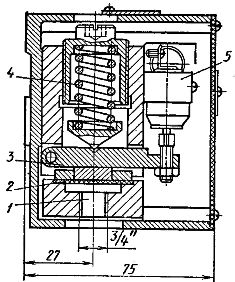
Rice. 6. Pressure switch
A change in the load on the hydraulic pipelines of metal cutting machines is accompanied by a change in oil pressure. A pressure switch is used to monitor the load (Fig. 6). When the oil pressure rises in pipe 1, the oil-resistant rubber membrane 2 flexes. In this case, the lever 3, pressing the spring 4, rotates and presses the microswitch 5. The relay is designed to work with a pressure of 50-650 N / cm2.