Rectifier units for traction substations
 A semiconductor rectifier, depending on the rectification circuit adopted and the power transformer coupling circuit, can be included in a bridge or neutral circuit.
Rectifier units for traction substations of urban electric transport VAK-1000/600-N, VAK-2000/600-N and VAK-3000/600-N. Designations of unit types are deciphered as follows: rectifier with silicon valve rectifier, for nominal rectified current 1000, 2000 or 3000 A, nominal rectified voltage 600 V, operating in accordance with zero circuit.
The unit consists of a power transformer, a rectifier, a control cabinet, protective cabinets or panels, and a high-speed cathode switch.
Rectifiers according to rectifier types are designated as BVK-1000/600-N, BVK-2000/600-N and BVK-3000/600-N, which means: silicon rectifier for rated rectified current 1000, 2000 or 3000 A, nominal rectified voltage 600 V operating on neutral circuit.
Each phase or arm of the rectifier unit consists of valves connected in parallel and series.
Parallel connection of valves is used when the rated current of the phase or leg exceeds the rated current of the individual valves.
Series connection of valves is used to ensure the dielectric strength of a phase or arm in the non-conducting part of the period when reverse voltage is applied to the phase.
The number of valves connected in parallel in phase or leg n1 is determined on the basis that the current of the phase or leg Ia of the rectifier must be less than the total rated current of the valves connected in parallel
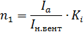
where Ki — factor of safety current taken equal to 1.35-1.8.
When valves are connected in parallel, the current between them is distributed unevenly, leading to overheating and faster failure of high-current valves and underutilization of current valves. The uneven distribution of current between valves connected in parallel is due to the fact that the valves in practice differ somewhat from each other in their direct branches of current-voltage characteristics and thermal resistances.
To equalize the current between valves connected in parallel, ohmic resistances connected in series with the valves or inductive current dividers can be used.
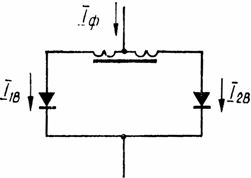
Rice. 1. Diagram of an inductive current divider for two valves connected in parallel: If — phase current, I2v, I1v — valve current
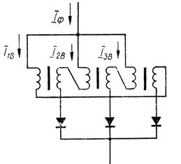
Rice. 2. Schematic of an inductive current divider for three valves connected in parallel
Ohmic resistances connected in series with the valves are rarely used due to the appearance of additional losses and a decrease in the efficiency of the rectifier.
In high power installations, inductive current dividers are usually used.
In fig.1 shows a diagram of an inductive current divider for two valves connected in parallel. The separator consists of a steel core on which two identical coils are wound, connected in such a way that the magnetic fluxes generated by them are opposite in direction.
With the current inequality in the parallel branches, the resulting magnetic flux appears in the core, which creates an additional voltage drop in the winding with a smaller current. This achieves an equalization of the current in the windings and in parallel-connected valves. A small amount of e is required to equalize the current in parallel valves. so the divider windings consist of a small number of turns.
In fig. 2 shows a diagram of an inductive current divider for three valves connected in parallel. The splitter consists of a three-bar magnetic core with two coils on each strip. Each of the parallel-connected valves is connected to the phase through two series-connected coils located on different bars. As the current increases in one parallel branch, an additional e is induced. etc. v. in the other two branches, thus equalizing the current in the windings of the divider and valves.
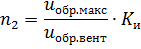
Splitters are implemented in the same way with a larger number of gates connected in parallel. The number of valves connected in series in each leg or phase is chosen so that the total rated reverse voltage of all valves connected in series is greater than the maximum reverse voltage applied to the arm or phase with the selected correction circuit (bridge or zero )
where Σrev.vent is the sum of nominal reverse series-connected valves, max is the maximum reverse voltage per phase or arm for a given rectifier circuit, Ki is the voltage safety factor taken equal to 1.45-1.8.
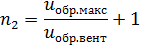
Hence the number of gates connected in series n2 will
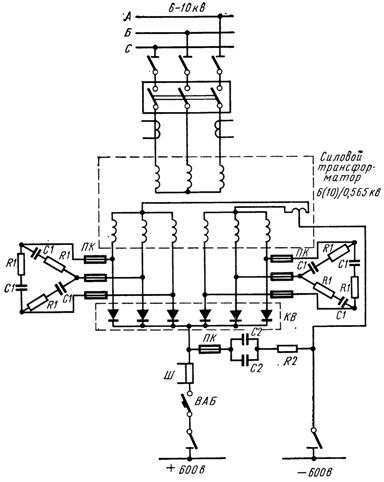
The number of avalanche valves connected in series is chosen equal to
In order to ensure an even distribution of the reverse voltage between the series-connected valves, a chain of series-connected shunt resistors RШ, with equal resistances, is connected in parallel to the valves, which serve as a voltage divider. The resistance value of the shunting resistors RШ is selected depending on the class and the number of valves connected in series in the range 1.5-5 kΩ.
The unevenness of the current distribution along the parallel branches of a phase or arm should not exceed ± 5% of the average measured current in the parallel branch, and at a load current above 100% of the nominal mode, the short-circuit current should not exceed ± 10%. The non-uniform distribution of reverse voltages in the valves shall not exceed ± 10% of the average operating reverse voltage applied to the valve.
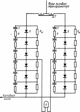
In fig. 3 shows the connection diagram of one phase of the BVK-1000/600-N rectifier unit.
BVK rectifiers with non-avalanche valves are factory built with AC surge protection cabinets and live sides removed.
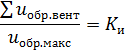
The surge protection on the AC side of these rectifiers consists of capacitors C1 and resistors R1 connected in star or delta, which are connected to the phases of the secondary winding of the transformer (Fig. 4).
Rice. 3.Connection diagram of one phase of BBK-1000/600-N
Rice. 4. Scheme of the VAK rectifier block with surge protection
This protection uses capacitors KM-2-3.15 with a capacity of 7.5-8 microfarads, resistors PE-150 with a power of 150 W and a resistance of 5 ohms, and fuses PK-3 with a fuse of 7.5 amperes.
Protection against switching overvoltages on the rectified current side is provided by two capacitors C2 IM-5-150, with a capacity of 150 microfarads, connected in parallel. Two 5 ohm resistors R2 are connected in series with them. Capacitors with resistors are connected between the positive and negative poles of the rectifier unit through a PK-3 fuse with a 50 A fuse.
Rice. 5. Transformer valve winding side surge protection circuit and rectified current
The overvoltage in the busbars of the DC switchgear, when a high-speed switch disconnects the short-circuit currents on the line, does not exceed 2 kV, i.e. does not exceed the dielectric strength of the series circuit of the valves. But the valves can be affected by surges resulting from the addition of surges when short-circuit currents in the line are switched off by high-speed switches with surges from switching currents in the valves themselves.
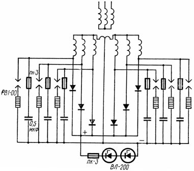
To protect semiconductor rectifiers from overvoltage, a circuit using arresters and capacitors is recommended (Fig. 5). RV1-00 limiters are fitted on the valve side of the transformer, including one between each phase and the neutral or negative terminal of the transformer.Due to the fact that the limiters are triggered for a time of 2 to 20 μs, and overvoltages appear in fractions of a microsecond, it is necessary to install capacitances of 0.5 μF in parallel with the limiters. Capacitances are connected to the valve coils through PK-3 fuses.
On the side of the rectified current between the positive and negative poles, the avalanche valves are turned on with a total avalanche voltage of 900 — 1000 V. The valves are connected to the positive bus through PC-3 fuses. Structurally, this protection is a getinax panel with fuse, two VL-200 avalanche valves and two mounted resistors. The panel is installed in the cage with a cathodic switch. In fig. 6 is a dimensioned view of the rectified current side surge protection panel.
In order to protect against atmospheric overvoltage, it is recommended to install terminal blocks on the positive (both trolley lines and negative) pole of the overhead line.
Due to the fact that avalanche valves can briefly pass significant currents in the opposite direction, connected in parallel with the valves, the RШ and R — C circuits may not be installed. Therefore, the BVKL rectifier blocks do not have R — C circuits, which simplifies the block diagram. However, to ensure proper operation, the circuit for monitoring the condition of the valves of the circuit RSh was also retained in the rectifier blocks with avalanche valves.
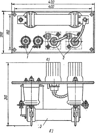
Rice. 6. Surge protection panel on the rectified current side: a — front view, b — top view, 1 — resistors, 2 — avalanche valves, 3 — fuse PK -3
Control of the state of the valves is carried out by specifying the relays (mixers) connected to the midpoints of the parallel branches of the valves of each phase or arm, which have the same potential (or a very small potential difference due to the differences in the characteristics of the valves).
In the event of a valve failure in any arm of a parallel valve branch, due to a change in the resistance of this arm, a potential difference occurs between the connection points of the blenders, which is sufficient for the blender to operate and close the Contacts.
The blender contact closes the circuit of each secondary winding of the TC signal transformer, thereby causing a change in magnetic flux in the magnetic circuit and actuating the protection relay, which in turn closes the circuit to a signal or to trip the rectifier unit. The signal transformer simultaneously isolates the extinguisher contacts from 220 V circuits.
The control cabinet panel next to the blenders shows the phase and parallel circuit numbers between which the blenders are connected. A dropped flag on the quencher indicates which circuit to look for faults.
Rectifiers are made in the form of frame metal cabinets with double doors, front and back doors and removable side walls. Inside the cabinets are mounted removable panels of insulating material, on which valves with coolers are attached. The valves of one series circuit are attached to each panel.
In order to provide greater dielectric strength to the rectifier unit, to reduce the possibility of overlapping between the valves or their air coolers, the valve panels in the cabinet are placed in such a way that there is as little potential difference between them as possible .
Inside the cabinet, on one side, there are AC busbars to which parallel valve branches are connected via current dividers. The supply of anode wires from the transformer to the busbars can be done both from below and from above. On the other side, there is a cathode strip with a shunt. The rectifier housing is installed in such a way that it is possible to service it not only from the front and back, but also from the side.
A fan is mounted on top of the cabinet, which creates a flow of cooling air from the bottom up. An air relay is mounted on the fan housing, which controls the flow of cooling air.