Determination of the resistance of natural grounded electrodes to leakage current
 Determining by calculation the resistance of natural grounded electrodes to current propagation is possible only very approximately. The actual value of the resistance of all natural earthed electrodes is determined by measurements carried out after the completion of the construction and installation works. If, as a result of the measurement, the actual value of the resistance turns out to be greater than the normalized value, then an additional grounding device is created from the required number of grounded electrodes.
The number of natural earthing electrodes whose current spreading resistance can be approximated in the calculations include water supply and lead cable sheaths.
A water supply system can create very little resistance to current propagation if it is made of steel pipes without corrosion-resistant insulation with welded joints (Table 1).
Length of underground pipe section, m Resistance in ohms for pipe diameter 1.5 2.5 4 6 100 0.47 0.35 0.28 0.23 500 0.37 0.29 0.4 0.19 1000 0 .30 0.25 0.20 0.17 2000 0.26 0.20 0.17 0.15 Sec. 1. Current propagation resistance of metal pipelines laid at a depth of 200 cm at ρ = 1 x 10⁴ ohm x cm
With a soil resistance other than 1 x 10⁴ ohm x cm, the values given in the table must be recalculated. Since the water supply system is laid below the depth of freezing or drying of the soil in summer, the resistance of the water supply system can be considered constant throughout the year.
Lead sheaths of cables laid in the ground become natural grounding devices only after a certain time of operation, when, as a result of the gradual destruction of the jute sheath, the metal sheaths of the cables come into direct contact with the ground. The resistance to current propagation of the lead sheaths of cables that are in the ground for a long time can be approximately determined from Table. 2.
Length of underground cable section, in m Dispersion resistance in ohms with cable cross-section, in mm2 16-35 50-95 120 and higher 50 2.1 1.6 1.2 100 2.0 1.5 1 ,1 200 1.8 1.4 1.0 500 1.4 1.1 0.8 1000 1.2 0.9 0.7
Section. 2. Resistance to current propagation of lead sheaths of cables laid at a depth of 70 cm at ρ = 1 x 10⁴ ohm x cm
Given in table.2 values must be recalculated proportionally ρ and multiplied by the seasonality coefficient determined by the table. 3.
Climatic zone Seasonality factor I 7 II 4 III 2 IV 1.5
Section. 3. Average values of seasonality coefficients
With several cables in the same trench, the total resistance of their lead sheaths to leakage current, taking into account the effect of mutual shielding, is given by the expression:

where Ro.k — resistance to current spreading of the lead sheath of one cable, n — number of cables in one trench.
The total resistance of natural earthed electrodes to current propagation is determined by the formula:
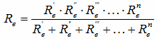
where R.c — propagation resistance of individual grounded electrodes, including individual branches of branched pipelines.