Telemechanization of electrical installations
 The purpose of telemechanical devices is to monitor and control the mode of operation of scattered electrical installations from a central point, which is called a dispatch point (DP), where the duty dispatcher is located, whose functions include operational impact on power plants. Telemechanical devices are subdivided into telesignaling (TS), telemetry (TI), telecontrol (TU) and telecontrol (TR) systems.
The vehicle system transmits object location signals as well as emergency and warning signals from the controlled point (CP) to the DP.
The TI system transmits quantitative data about the state of the managed object to the DP.
Remote control system TU transmits control commands from DP to CP. The TR system transmits control commands from the DP to the KP.
Signals from DP to CP are transmitted via communication channels (CC)… Cable lines (control cables, telephone cables, etc.), Power lines (HV overhead lines, N.N. distribution network, etc.) and special communication lines (radio relay, etc.).
The signal transmission process is shown in Fig.1, where IS is a signal source, P is a transmitting device, LAN is a communication line, PR is a receiving device, and PS is a signal receiver (object).
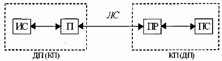
Fig. 1. Scheme of signal transmission through the communication line from the control point to the controlled point.
With TS, TI on the control panel there are IS, P, on DP — PR, PS. Information (informative) information, discrete signals reflecting a finite number of states of objects (TS), and analog or discrete signals reflecting a set of states (TI) are transmitted over the LAN.
With TU, TR on DP we have IS, P, on KP — PR, PS. Administrative (control) information, discrete control signals for a limited number of entity states (TC), and analog or discrete signals for a set of entity states (TR) are transmitted over the LAN.
Thus, the direction of the signals for TS, TI is one-way, and for TU, TR it is two-way, since for the state of TU it is necessary to reflect the state of the object by means of TS, and for TR- by means of TI. Signaling and propagation can be qualitative (binary) in nature and quantitative (multiple) - analog or discrete.
Therefore, telemechanical systems often perform dual functions: TU — TS and TR -TI. Since the signals are exposed to interference, then to increase the noise immunity and selectivity of the receiving device, the analog signals are encoded, that is, they are subtracted and the information is presented in the form of discrete signals - signals according to the coding algorithms, when each signal corresponds to its own combination from discrete signals.
Encoding the signal
The advantage of telemechanical devices compared to remote monitoring and control devices is the reduction in the number of communication channels.In remote devices, communication channels are spatially separated — each channel has its own LAN. In telemechanical devices, there is only one communication line, and communication channels are formed due to time, frequency, phase, code and other channel separation methods, and a much larger amount of information and administrative information is transmitted on one channel.
A discrete information signal is a number of pulses that differ from each other qualitatively (polarity, phase, duration, amplitude, etc.).
Coding a single-element signal allows a limited amount of information to be transmitted even when using several functions. A much larger amount of information can be conveyed by multi-element encoding, even when only two functions are used.
Single-element coding is widely used in telemechanical devices due to the fact that many controlled and monitored objects are two-position and require the transmission of only two command signals. Multi-element coding is used in cases where the number of controlled and monitored objects is large, or when the objects are multi-positional and accordingly require the transmission of many commands.
In TU — TS codes are used to transmit independent commands. In TU — TS, pulse duration or frequency are usually used as selectors. In the TI — TR systems, codes are used to transfer numerical values and are called arithmetic codes. At the heart of these codes are systems for representing numbers through code sequences.
Remote control system - telesignaling (TU - TS)
In TU — TS systems, the transmission of a control command can be divided into two positions:
1) the choice of this object (choice),
2) transmission of command.
Separation of signals transmitted over a LAN is done in different ways: through separate circuits, during transmission, through selective characters during encoding.
TU — TS systems with switching (in separate circuits), time division and signal frequency are widespread.
The commutation-split system is shown in Fig. 2.
The control object is a switch with auxiliary contacts Bl, B2. The system uses four selective signal signs - positive and negative polarity and two amplitude levels, therefore four signals can be transmitted on one two-wire line: 2 command signals (on-off) and 2 warning signals (off, on).
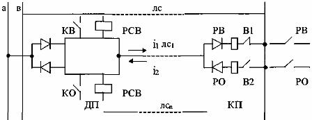
Rice. 2. Schematic diagram of the TU-TS system with separation of switching signals.
The total number of signals represented in a circuit-switched system is: N = (k-l) m
If there is a minimum level of the warning signal in LC1 (half-wave command rectified current i1), the RCO is triggered. When KB is on, the distribution signal «on» is applied to turn on the switch, while B2 is closed and the minimum level of the signal signal (half-wave rectified current i2) arrives at LS1, the relay on the PCB is activated. When the KO is turned on, a process similar to turning on the HF occurs.
Such TU-TS systems with separation of switching signals are used to control a limited number of objects at a distance of up to 1 km.
The TU-TS system with time-division signals transmits signals to the LAN sequentially, it can work cyclically, constantly monitoring the object or sporadically, if necessary. The system diagram is shown in fig. 3.
The LAN communication line using synchronously switching distributors P1, PG2 is sequentially connected in steps n, n-1 to the corresponding control circuits, and in steps 1, 2 ... to the signal circuits.
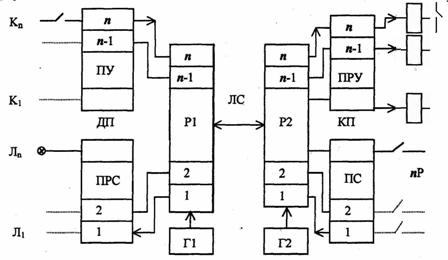
Rice. 3. The basic TU-TS system with time division signals.
The selection of signals in this system can be direct — according to a single selective characteristic (as shown in the diagram), or combined — according to a combination of selective characteristics. In direct selection, the number of signals transmitted through the LAN is equal to the number of steps of the distributor: Nn = n In combined selection, the number of signals increases: Nk = kn, where k is the number of combinations of characteristics.
In this case, the system is complicated by the appearance of scramblers and decoders on the sides of DP and KP.
The TU-TS system with partial signal separation transmits signals to the LAN continuously because the start of the communication is distributed by frequency. In this way, several signals can be transmitted simultaneously over the LAN. The system diagram is shown in fig. 4.
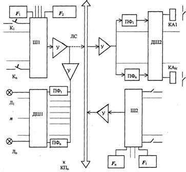
Rice. 4. Schematic diagram of the TU-TS system with frequency division of the channels
On DP and KP there are generators with stable frequencies f1 ... fn, which are connected to encoders NI (DP), Sh2 (KP). Control buttons K1 … Kn and object relay contacts P1 … Pn.
If the coding is single-element, then each distributed and signaling signal has its own frequency.
The separation of the signals is done by band-pass filters PF in DP and CP, therefore it is in principle possible to transmit all signals simultaneously. Multi-element coding allows you to reduce the number of generators and bandpass filters, as well as narrow the signal bandwidth.For this, encoders and decoders are used on the sides of DP and KP, which encode and decode signals.
The TU-TS system with time and frequency division of channels is currently built on logic elements using microcircuits.
Telemetry Systems (TI)
In the TI system, the transfer of the renewable energy parameter consists of three operations:
1) selection of expansion object (measured parameter)
2) quantity conversion
3) transfer.
On the CP, the measured parameter is converted to a value that is convenient for distance transmission, on the DP, this value is converted to the readings of a measuring or recording device.
Separation of signals transmitted over LAN is also done by switching, time, frequency method and code division of signals is also used. TI systems are diverse in terms of signal type. A distinction is made between analog, pulse and frequency systems.
In analog systems, a continuous value (current, voltage) is transmitted to the LAN. In a pulse — a sequence of pulses or a code combination. In frequency — alternating current of sound frequencies.
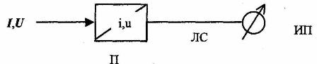
Rice. 5. Block diagram of an analog telemetry system.
The analog TI system is shown in Fig. 5. The transmitter, in whose capacity the converter P of the corresponding parameter to current (voltage) is used, is connected to a LAN line.
The transmitter is usually rectified (current, voltage) or inductive (power, cos) converters. Typical current (VPT-2) and voltage (VPN-2) converters are shown in Fig. 6 and 7.
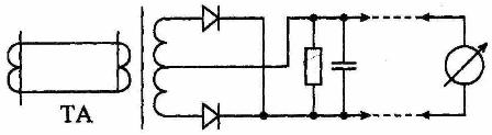
Rice. 6. Circuit diagram of a rectifier (VPT-2)
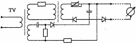
Rice. 7. Rectifier converter scheme (VPN-2)
Pulse TI systems have several varieties that differ in the ways of representing the analog parameter by pulse signals. There are digital pulse, code pulse, and pulse-frequency TI systems using the corresponding converters shown in Fig. eight.
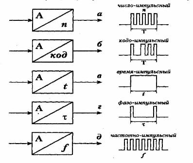
Rice. 8. Analog parameter to pulse signal converters.
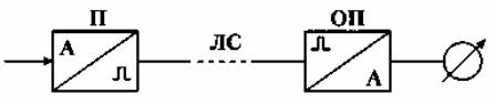
Rice. 9. Block diagram of the pulsed TI system
The pulse system TI is shown in Fig. 9. The transmitter is the corresponding converter P which sends pulses to the LAN which are analog values according to their characteristic parameters. The reverse conversion is done by the OP converter. TI pulse systems transmitters are chip pulse generators.
Frequency TI systems use sinusoidal signals, with their frequency representing an analog parameter. Frequency systems use transducers — generators of sinusoidal oscillations controlled by current or voltage.
The TI frequency system is shown by the block diagram in Fig. eleven.
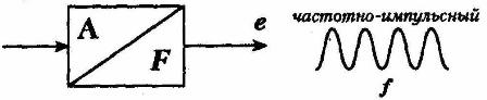
Rice. 10. TI frequency system converter.
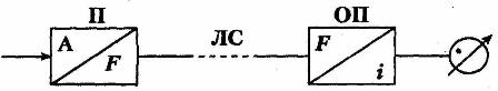
Rice. 11. Block diagram of the TI frequency system.
The inverse conversion performed by the OP can be done either to an analog value or to a decimal code for indication by digital instruments with an ADC.
Pulse and frequency TI systems have a large measurement distance, cable lines and overhead lines can be used as communication lines, they have high noise immunity, and can also be easily input into a computer using appropriate frequency codes, code converters codes.