Rails for lifting and transporting devices
 Powering electrical receivers on mobile lifting and transport devices — cranes, hoists, and trolleys — can be accomplished either by flexible cable or by means of trolleys, which are bare wires from which the current is drawn from sliding pantographs.
Flexible cables suspended on a rope on rings, rollers or movable carriages or wound on special cable drums are used for power supply in cases where:
a) strollers cannot be placed due to lack of space,
b) the device of carts is generally unacceptable (for example, in explosive areas),
c) the lifting and transporting mechanism is used occasionally (for example, when repairing equipment) and has a short travel duration.
 The field of application of flexible cables is mainly limited to hoists for installation and repair.
Trolleybuses are mainly used to power lifting and transport devices.
Carts are mainly made of steel with different profiles (angle, square, channel, two-line), the most common of which is an isosceles angle, and are laid along special structures on insulators with holders.
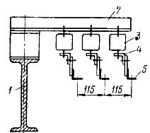
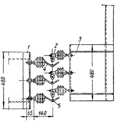
Laying of angle steel bogies on monorails: 1 — monorail, 2 — support structure, 3 — bogie insulator, 4 — holder, 5 — trolleys.
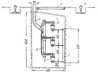
Laying in the channel channels for feeding the bogies: 2 — supporting structure, 2 — trolley insulator, 3 — structure for fixing the pantograph, 4 — pipe for wires, 5 — movable plate, 6 — running rail of the trolley track, 7 — pantograph shoe, 8 — trolls.
 It is also possible to use bare round or profiled wires - copper, aluminum or steel for trolley lines. The laying of such lines can only be done in the form of a free suspension, less reliable than the rigid attachment of trolleys.
It is recommended to install angle steel trolley structures on crane beams every 3-3.5 m, trolley structures are installed every 2 m on straight sections and every 1 m on curves. For long trolleybuses, it is necessary to install temperature compensators approximately every 50 m and in the places of expansion joints of buildings.
Trolleys should be placed on the side of the section opposite to the location of the crane cabin, exceptions are allowed in cases where the trolleys are not accessible for accidental touch from the cabin, landing platform and stairs.
Free suspension of trolley wires: 1 — structure for attaching trolley holders, 2 — pantograph, 3 — structure for attaching pantographs, 4 — wire holder, 5 — wire for trolleys.
The trolleys may be supplied either by separate lines from the substation switchboard, or from the nearest workshop distribution point, or, finally, from branches from the main bus trunks. The most widespread is the supply of trolley lines from shop distribution points and buses.
Using separate feeders from the main switchboards of substations can be recommended only in relatively rare cases, namely for powering trolleys with sufficiently powerful cranes (for example, in open, mobile, etc. shops).
Typical power supply schemes for trolley lines are typical:
a) from one place to one point on the line,
b) the same, but with induction feeding with aluminum tape,
c) same but with non-inductive feed,
d) from two or more places to the corresponding number of points on the line.
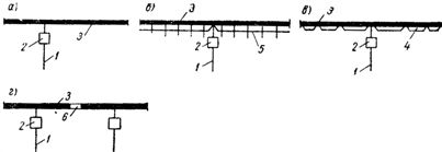
Power circuits for trolley lines: power feeder, 2 — control apparatus, 3 — trolley line: 4 — cable or wire feed, 5 — aluminum tape feed, 6 — insulating insert.
Supplying the line to one point without recharging is possible when in the line, the cross-section of which is selected according to the average current, the voltage loss at the peak current does not exceed the permissible value, counted from this point to the farthest end of the line.
The most advantageous point of feeding the line will be that which, on the one hand, provides the shortest length of the feeder feeder, and on the other hand, allows maintaining within the permissible value of voltage loss.Fed circuits, as well as multi-site feeder circuits, are used when the voltage losses in the network at peak current exceed permissible values.
The make-up can be done in two different ways: a) with an aluminum strip placed and fixed on the same holders as the trolls, b) with wire in steel tubes or with a cable according to the Kopitov method.
According to the first method, makeup is inductive and practically continuous. According to the second method, the make-up step is a calculated value, and the make-up is obtained stepwise and at the same time non-inductive.
It is recommended to resort to the second method only in cases where the aluminum strip supply is significantly underutilized for heating, which can happen with a long line length and a relatively small calculated rms current.
Carts fed from several places to the corresponding number of points are divided into sections according to the number of feeding points. The section is made by installing insulating inserts between the sections of the trolleys (for example, wooden blocks impregnated with an insulating mixture).
Sectional assembly can be performed in two ways:
a) with an insulating insert that is not covered by a pantograph, while at the moment when the pantograph passes through the section block, the possibility of parallel operation of the feeders supplying the sections is excluded, but there is a power interruption and, therefore, the shutdown of these electric motors on the tap, in the circuits of which there are devices with zero windings,
b) with an insulating insert of such a length that there will be no interruption of the supply to the tap, while at the moment when the pantograph passes through the section block, parallel operation of the feeders supplying the sections will take place and equalizing currents will appear with one or another value depending on the different voltages of the power supply devices.
Since large equalizing currents can lead to blown fuses and overheating of wires and cables, the implementation of the section assembly according to the second method can be recommended only in cases where different sections of the trolley are powered by the same transformer.
Favorable conditions for the sectioning of trolley lines are created when they are fed by power channels, which, like trolleys, are usually placed along the shops. In this case, separation, which is always desirable for operational reasons, should be widely applied, whether required by design conditions or not.
When making a final decision on the choice of power scheme, it should be borne in mind that in some cases it may be more advantageous to increase the cross-sections of the power supply devices relative to those selected by the rms current than to use makeups or power in a few points. This leads to the need for a technical and economic comparison of the options.
In places where power is supplied to trolley lines, devices must be installed with the help of which the lines can be disconnected at any time. For this purpose, the distribution boxes of the YRV type are most convenient.
With free suspension of trolley wires, when safety rules require automatic disconnection of the line power supply in case of wire break, instead of knife switch a push-button contactor is installed.
In conclusion, the so-called Method of feeding trolleys, used in cases where the construction of trolleys along the line of motion of the lifting and transporting device is impossible.
In this method, the trolleys (in the form of short-length segments) are mounted directly on the lifting and transport device itself, and the pantographs are located on supports along the travel path. The length of the carts should be slightly greater than the distance between the supports to avoid power interruptions.