Electric substations: purpose and classification
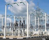 An electrical substation is an electrical installation that serves to transform and distribute electricity. and consists of transformers or other energy converters, switchgear, control gear and auxiliary structures.
Depending on the function, they are called transformer (TP) or transformers (PP). The substation is called a complete substation — KTP (KPP) — when supplying transformers (converters), low-voltage switchboard and other elements assembled or in visa fully prepared for assembly.
Electric substations are used to receive, transform and distribute electricity, they are carried out at all voltage levels, they can increase if they are located in close proximity to power plants and convert electricity with a higher voltage than them in the network) or lowering (these include the huge number of substations from which electricity is supplied to consumers).
The purpose, power and voltage levels of an electrical substation are determined by the layout and configuration of the electrical network in which it operates, by the nature and loads of the connected electrical consumers.
There are mainly the following types of electrical substations:
-
dead end (end);
-
branch lines connected to overhead lines passing nearby;
-
intermediate, serving to feed consumers;
-
transit (in a large number of cases — nodal), intended not only for powering consumers, but also for transmitting energy flows to neighboring networks of own and neighboring power systems;
-
converter — for transmission and reception of electrical energy at direct current;
Structurally, the distribution devices of electrical substations can be open (the main equipment is located outdoors) or closed (in urban conditions, in places with unsatisfactory environmental conditions), depending on their departmental affiliation, substations are operated by electrical systems or industrial and other electricity consumers.
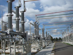
AC electrical substations of higher voltages 330, 500, 750 kV, 150 kV and some of the 220 kV substations with a developed electrical connection scheme, equipped with synchronous compensators 50-100 MB-A and higher with an open switchgear , a large number of transformers, circuit breakers, etc. With the help of these substations, as a rule, intersystem communications are carried out, forming a single and unified power system.
Substation 330 kV Mashuk
Permanent substations with higher voltages 800 and 1500 kV with a large number of complex conversion equipment are still few. In the future, however, their importance will increase significantly.
Closed deep entrance substations with high voltage 110-220 kV, the construction of which is carried out in densely populated areas of large cities, where only limited areas can be allocated for construction and where significant municipal and industrial loads are concentrated. In such substations, they provide constant monitoring and the necessary measures to protect the population from noise generated by operating transformers and other equipment.
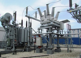
Electric substations 35, 110 and 220 kV with a simplified diagram of electrical connections, often without switches on the high voltage side, with complete switchgears for low voltage (KRU, KRUN, etc.), in which there is equipment for control, protection, signaling and automation located on the front of their cabinets and do not require a dedicated panel room.
These substations do not require permanent personnel on duty, are manned by operational field teams (OVB) or are on duty at home and are the majority of substations of this type in terms of number (to facilitate maintenance and dispatch control, the substations are equipped with appropriate communication and telemechanical devices).
110 kV substation built for the 2014 Winter Olympics in Sochi
Substations 6 — 10 kV for urban, village and rural purposes, serviced by field teams.
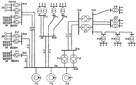
Rice. 1. Schematic diagram of the distribution of electricity from the power plant at voltages of 10 and 35 kV.
In the diagram of fig.1 shows that two parallel power lines L-7 and L-8 feed the regional (urban, industrial) step-down transformer substation P-7 for a secondary voltage of 10 kV, from which the step-down substations of consumers-P- 8, P- 9, P- 10 and others. Energy consumers are fed from the buses of these substations (as well as from the buses of the P-1, P-2 and P-3 substations).
Feeding step-down substations directly from the busbars of stations or regional substations (substations P-1, P-2, P-3, P-8, P-9) is recommended only with sufficiently powerful and critical substations. Groups of small substations are usually more expedient to be fed from distribution points (DPs), feeding from the busbars of the station or district substation.
At the distribution point, the electricity is not transformed, as it is only intended for the distribution of electricity between individual step-down substations. City grid substations, workshop substations and even general plant substations can be powered by RP.
It is possible to supply several substations from one line without building a substation, as shown for substations P-10, P-11 and P-12. In both cases, the number of lines leaving the tracks at the station or district substation and the cost of building the network are reduced.
Substations P-10 and P-11 are checkpoints, all others are dead ends.
Powering substations with single lines, for example, powering substation P-1 on line L-1, does not provide continuous power, since a line failure or shutdown for repair results in a long interruption of power to the users of the substation.To prevent this, the power supply to the substation is backed up, for example, by building two power lines: lines L-3 and L-4, feeding substation P-3, L-3 and L-6 lines, feeding RP, etc. ., the power supply to the corresponding substation continues continuously through the second line.