One-line diagram of the traction substation
 In urban settings, traction substations receive electricity from the feeder center, usually through cable glands. Three-phase alternating current of 6 or 10 kV is supplied through the inputs through line disconnectors, high-voltage switches, current transformers and bus-to-bus disconnectors distribution devices 6 or 10 kV substations. The electricity from the busbars is distributed to converter blocks and auxiliary transformers.
Current and voltage transformers are installed in switchgear 6-10 kV to power measuring devices, relay protection and measuring instruments. Most voltage transformers are connected directly to the bushings after the line disconnectors. This connection enables constant monitoring of the supply cable voltage even when the high voltage switch is turned off. The voltage transformer is protected by fuses.
Buses are double and single. In tram and trolleybus traction substations, single busbars divided by disconnectors into two or three sections are usually used.
The converter block consists of a power transformer, to the secondary winding of which the rectifier anodes are connected. The primary winding of the power transformer is connected to the 6 or 10 kV busbars through a disconnector, high voltage switch, current transformers.
Rectifier current from the cathode of the rectifier flows through the shunt automatic high-speed switch and disconnector to the main positive bus of the substation.
The negative pole of the rectifier block is the midpoint of the rectifying reactor connecting the neutral points of the two reverse stars of the secondary winding of the power transformer. The center point of the equalizing reactor is connected through a disconnector to the negative bus of the substation.
From the positive bus through bus disconnectors, line breakers, shunts, spare bus switches through the 600 supply cables, the rectified current enters the catenary of the tram and trolleybus lines. The current circuit is closed through the rolling stock power equipment, rails and ground or negative conductor, suction cables and disconnectors to the negative bus of the substation.
In the 600 V current switchgear, a spare positive bus with a spare switch is also installed, which allows the audit and temporary replacement of each of the line switches without de-energizing the line and transferring the load to or from the adjacent substation .
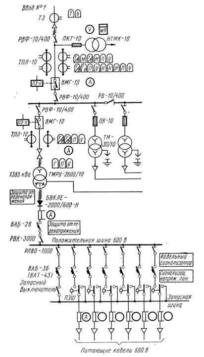
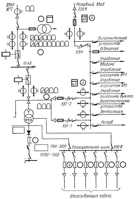
Rice. 1. One-line diagram of a traction substation
Single substations operate in a decentralized overhead power system.In such a system, each single substation feeds two sections of the catenary network, and a section isolator is installed in the network at the traction substation. Each section of the contact network is fed in parallel by two adjacent substations (Fig. 2). From the substation there are two positive power cables and two negative suction cables. The positive power cables are protected by high-speed circuit breakers.
In the event of failure of a single substation in the decentralized power system, it is completely unloaded by neighboring substations. In this case, in order to maintain a parallel feed of the overhead line from the adjacent substations that remain in service, each substation has a section switch that automatically turns on when the line switches connecting both sections fed by that substation are turned off.
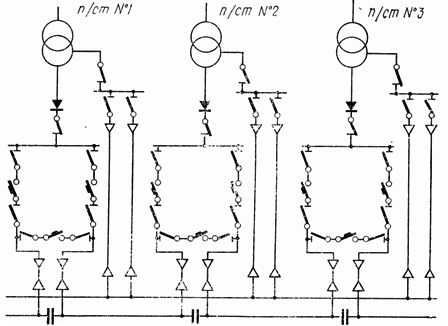
Rice. 2. Feeder circuits of the contact network from single substations
One or two auxiliary transformers connected to 6 or 10 kV AC busbars through disconnectors and fuses are installed to supply the users of auxiliary needs of the traction substation. In order to supply the most critical users with their own needs in emergency modes, they organize backup inputs of three-phase alternating current with a power of 5-10 kW and a voltage of 220 V from a source that does not depend on the presence of voltage on the buses at 6 or 10 kV at the traction substation.
If the 6-10 kV bushings of the substation work in series, if it is impossible to put a spare 220 V bushing, two auxiliary transformers are installed at the substation, one of which, as usual, is connected to the 6-10 kV busbars and is a working transformer, and the other to the reserve input 6-10 kV before the switch instead of the measuring voltage transformer and serves as a reserve to supply consumers with their own needs in the event of a voltage failure at the input, while performing the functions of a voltage transformer for controlling the backup input voltage.
In this case, the voltage transformer is connected to the 6-10 kV busbars for powering the measuring and measuring devices. In order to account for the power consumption of the transformer connected to the backup input, separate measuring devices are installed on it.
Traction substations are designed, built and operated in accordance with the applicable rules, which are mandatory for all such devices. The main ones are "Rules for electrical installations", "Rules for the technical operation of consumer electrical installations and Safety rules for the operation of consumer electrical installations", as well as instructions and rules issued by the organization responsible for the traction substation.