Coefficients for calculating electrical loads
 The task of calculating electrical networks is to estimate the values correctly electrical loads and the selection, respectively, of the smallest of the possible cross-sections of wires, cables and busbars where the standardized conditions would be met with respect to:
1. heating wires,
2. economic current density,
3. electrical protection of individual sections of the network,
4. voltage losses in the network,
5. the mechanical strength of the network.
The design loads for the selection of cross-sections of wires are:
1. half-hour maximum I30-for selection of heating cross-sections,
2. the average switching load Icm — for choosing the cross-sections for the economic current density,
3. peak current — for selection of fuses and current settings of overcurrent circuit breakers and for calculation of voltage loss. This calculation usually boils down to determining the voltage loss in the supply network when starting individual high-powered squirrel-cage motors and in trolleybuses.
When choosing the cross-sections of the distribution network, regardless of the actual load factor of the electrical receiver, the possibility of using it at full capacity must always be taken into account, and therefore the rated current of the electrical receiver must be taken as the rated current. An exception is allowed only for wires to electric motors selected not for heating, but for overload torque.
Thus, for the distribution network, settlement as such does not take place.
To determine the estimated current in the supply network, it is necessary to find the combined maximum or average load of a number of energy consumers and, as a rule, different modes of operation. As a result, the process of calculating the power network is relatively complex and is divided into three main sequential operations:
1. drawing up a calculation scheme,
2. determination of the combined maximum load or its average values in individual sections of the network,
3. selection of sections.
The design scheme, which is a development of the power supply concept outlined when considering the distribution of electrical energy, must contain all the necessary data regarding the connected loads, the lengths of the individual sections of the network and the chosen type and method of laying.
The most important operation — the determination of electrical loads on individual sections of the network — is, in most cases, based on the use of empirical formulas. The coefficients included in these formulas depend to the greatest extent on the mode of operation of consumers of electrical energy, and the correct assessment of the latter is of great importance, although it is not always accurate.
At the same time, the incorrectness in determining the coefficients and, accordingly, the loads can lead to either insufficient bandwidth of the network or an unjustified increase in the price of the entire installation.
Before moving on to the methodology for determining electrical loads for power networks, it should be noted that the coefficients included in the calculation formulas are not stable. Due to continuous technological progress and the development of automation, these factors must be subject to periodic review.
Since the formulas themselves and the coefficients included in them are approximate to a certain extent, it should be borne in mind that the result of the calculations can only be the determination of the order of interest amounts. For this reason, excessive scrupulousness in arithmetic operations should be avoided.
Values and coefficients included in the calculation formulas for determining electrical loads
Installed capacity Ru means:
1. for electric motors with continuous operation — nominal power in the catalog (passport) in kilowatts, developed by the shaft motor:

2. for electric motors with intermittent operation — nominal power reduced to continuous operation, i.e. to PV = 100%:
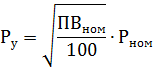
where PVN0M is the rated duty cycle in percent according to catalog data, Pnom is the rated power at PVN0M,
3. for electric furnace transformers:
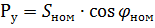
where СХ0М is the rated power of the transformer according to catalog data, kVA, cosφnom is the power factor characteristic of the operation of an electric furnace at rated power,
4. for transformers of welding machines and devices — conditional power reduced to continuous operation, i.e. to PV = 100%:
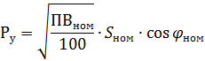
where Snom is the duty cycle rating of the transformer in kilovolt-amperes,
Under connected power supply Ppr of electric motors is understood as the power consumed by the motor from the network at nominal load and voltage:

where ηnom is the motor rated power in relative units.
Average active load for the busiest shift Rav.cm and the same average reactive load Qcp, cm are coefficients divided by the amount of electricity consumed during the maximum loaded shift (WCM and VCM, respectively) by the duration of the shift in hours Tcm,


Average annual active load Rav.g and the same reactive load Qcp.g are coefficients from dividing the annual electricity consumption (Wg and Vg, respectively) by the annual working time in hours (Tg):


Under maximum load Rmax is understood as the largest average load for a certain time interval.
In line with PUE, for the calculation of heating networks and transformers, this time interval is set equal to 0.5 h, that is, the maximum load is assumed for half an hour.
Distinguish the maximum load for half an hour: active P30, kW, reactive Q30, kvar, full S30, kVA and current I30, a.
Peak current Ipeak is the instantaneous maximum possible current for a given consumer of electrical energy or for a group of electrical consumers.
Under utilization factor for change of KI understand the ratio of the average active load for maximum loaded displacement to the installed power:

Accordingly, the annual utilization factor is the ratio of the average annual active load to the installed capacity:

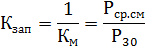
The maximum factor Km is understood as the ratio of the active half-hourly maximum load to the average load for the maximum loaded shift,

The inverse of the maximum coefficient is the filling coefficient of the Kzap graph
Demand factor Ks is the ratio of the active half-hour maximum load to the installed capacity:
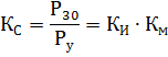
Under the inclusion factor Kv is understood as the ratio of the working time of the receiver of the repeated short-term and long-term mode of operation of a shift to the duration of the shift:

For electrical receivers designed for continuous operation during switching, the switching factor is practically equal to unity.
Load factor for active power K3 is the ratio of the load of the electrical receiver at a given time Pt to the installed power:
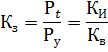
For electric motors, where the installed power is understood as the shaft power, it would be more correct to attribute Ki, Kv, K3 not to the installed, but to the power supply connected to the network.
However, in order to simplify the calculations, as well as due to the difficulties in accounting for the efficiency involved in the load of electric motors, it is recommended that these factors also refer to the installed power. Thus, the demand factor equal to unity (Kc = 1) corresponds to the actual load of the electric motor in the amount of η% of the full one.
Coefficient of combination of maximum load KΣ is the ratio of the combined half-hourly maximum load of several groups of electric consumers to the sum of the maximum half-hourly loads of individual groups:

With an approximation admissible for practical purposes, it can be assumed that
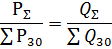
and consequently
