Checking secondary switching circuits while energized
Consider checking the operating circuits (control, protection, automation, signaling, blocking) under voltage.
The check of the live circuit is carried out with the supply circuit disconnected after checking the correct installation of electrical circuits, adjusting the equipment and testing the insulation. All contact connections of terminal blocks and devices (with a screwdriver), as well as the polarity of the supplied voltage, must also be checked in advance.
When the extra voltage is applied for the first time, make sure that there is no short circuit in the circuit. For this, only one fuse is installed, and instead of the second, the control lamp turns on. In the absence of a short circuit, the lamp does not light or does not shine at full brightness. This lamp should have the lowest possible internal resistance (lamp power on the order of 150-200 W).
When the voltage is applied through a lamp with high internal resistance to the relay coil of relatively low resistance, the glow of the lamp differs slightly from full. After applying the operating voltage, the accuracy of operation, the sequence of operation of individual contacts, relays and other elements and the entire circuit as a whole in all modes of operation provided by the circuit are checked.
The operation of the protection, alarm and automation circuits is checked by simulating emergency and abnormal modes of operation of the equipment by closing the hands of the contacts of the protective relay, process sensors, etc.
When checking a circuit under voltage, there may be cases of failure in the operation of individual elements and nodes of the circuit. Although damages and violations in schemes are extremely diverse, they can be attributed to the following main types:
a) open circuit;
b) short circuit;
c) grounding;
d) the presence of a bypass circuit;
e) non-compliance with the requirements of the scheme for parameters or malfunction of individual devices included in the scheme.
All these defects are not immediately detected and can have a wide variety of external manifestations, depending on the characteristics of the circuit. Only a thorough analysis of the circuit, careful checks and trials make it possible to quickly and effectively identify and eliminate a malfunction. Since each malfunction in the circuit requires a special analysis, the method of identifying a defective element cannot be presented in the form of a general guide suitable for all possible cases.
The figure shows the circuit diagram for the operation of a spring-loaded oil circuit breaker.
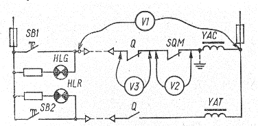
As an example, consider the simplest case of failure — a break in the circuit of the auxiliary contacts of switch Q. An external sign of failure — the HLG lamp is off. To identify a defective item, you must:
a) check the integrity of the fuses;
b) check the voltage on the HLG lamp (if there is no voltage on the lamp with additional resistance, then we can assume an open circuit in the switching circuit);
c) check the integrity of the signal lamp thread.
d) check the presence of a circuit of contacts Q and SQM by connecting a voltmeter in series parallel to contacts Q and SQM.
When a voltmeter is connected in parallel with the SQM contacts, the voltmeter reading is zero and therefore the SQM contacts are closed.
A voltmeter reading across the Q pins indicates an open circuit across these pins. When checking operating circuits, as a general rule, you should use a high-resistance voltmeter, as using low-resistance devices can cause circuit devices to operate falsely.
So, in the circuit under consideration (if the switching circuit is in good condition), connecting a test lamp in parallel with the signal lamp HLG with an additional resistance instead of a voltmeter can cause the switching coil YAC to actuate, which turns out to be connected in series with the test lamp and therefore spontaneously turning on the switch. Incandescent lamps can only be used when checking the integrity of fuses and determining a short circuit in the circuit.
In such cases, for example, with grounding (dotted line), pressing the power button causes the fuses to burn, so it is not possible to determine the fault using a voltmeter, as described above (the resistance of the series-connected coil is negligible compared to the internal resistance of the voltmeter). To determine the fault in the circuit, it is necessary to turn on the incandescent lamp in parallel with the power button, which in this case will burn at full brightness.