Methodology for determining electricity losses in lines, transformers and electric motors
Determination of power losses in the line
Power losses ΔE (kW • h) in the line, transformer for the accounting period (month, quarter, year) in production conditions, using the results of experimental measurements, it is recommended to determine from the expression

where Eh.s — electricity losses for a typical day of the accounting period, kW • h; n is the number of working days in the accounting period.
Weekend power losses are calculated separately.
The typical days of the accounting period are as follows:
-
according to the entries in the logbook, determine the energy consumption for the accounting time period;
-
according to the established consumption for the reporting period, the average daily consumption of electricity is established;
-
according to the logbook, a day is found that has the same (or close to it) energy consumption as the daily average value obtained above.
The days thus found and their actual load schedule are assumed to be typical.
The electricity losses in the accounting period row using the load schedule for a typical day can be calculated by the formula
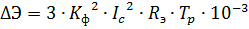
where Kf is the shape factor of the load graph; Ic is the average value of the line current for a typical day, A; Re — equivalent active resistance of the line, Ohm; Tr is the number of working hours for the accounting period.
For electrical loads of most industrial plants, Kf is usually in the range of 1.01-1.1. For an enterprise whose production program and technological process are fairly constant, Kf varies within very insignificant limits. Therefore, in order to calculate losses, this coefficient must be determined 3-5 times and, averaging its value over these readings, assume a constant within the reporting period.
Under operating conditions, Kf of the line can be calculated with sufficient accuracy according to the readings of the active energy meter by the formula
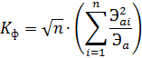
where n = t / Δt is the number of counter readings; t — time of determination of Kf, h; Δt — time of one marking, h; Eai-active electricity consumption for the i-th marking of the meter readings, kW • h; Ea is the consumption of active electricity for the time t determined by the meter, kW • h.
Average line current
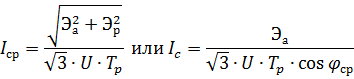
where Ea (Er) is the consumption of active (reactive) energy for a typical day, kW • h (kvar • h); U — line voltage, kV; Tr is the number of working hours in a typical day; cosφav — the weighted average value of the power factor for the time Tr.
Equivalent resistance in operation
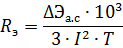
where ΔEa.s — losses of active energy of the branched network during the time T, kW • h; I is the current of the main part of the network, A.
Sometimes (for complex circuits) it is very difficult to determine the equivalent resistance using the readings of the instrument. In this case, they can be determined by calculation.
For a straight line with concentrated end load

where r0 is the active resistance at 1 m of the line; l — line length, m.
For the branched line shown in Fig. 1,
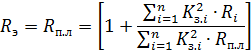
where Rp.l. — active resistance of the supply line; Ri is the active resistance of the i-ro line section from the end of the supply line to the load; K3i = Pi / P1 — load factor of the i -th compared to the most loaded section, taken first.
The above formula is derived under the assumption that the power factors of the sections are approximately equal to each other.
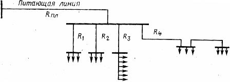
Rice. 1. Power circuit for the load away from the TP workshop rails
Determination of power losses in transformers
Losses of active electricity in transformers for the reporting period
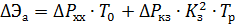
where ΔPXX. — idle power losses, kW; ΔРКЗ — short-circuit power loss, kW; T0, Tr — the number of hours of connection of the transformer to the network and the number of hours of operation of the transformer under load for the reporting period; Kz = ICp / Inom. t is the current load factor of the transformer; ICp — average current of the transformer for the reporting period, A; Inom t is the rated current of the transformer, A.
See here for more details: How to determine the loss of electricity in a power transformer
Determination of power losses in electric motors
For large units (mills for grinding chips and fibers, chips, compressors, pumps, etc.) it is necessary to take into account the losses of electricity in the motors and in the mechanisms driven by them in the electrical balance of the unit.
During stationary operation of electric motors, the losses in them are determined as the sum of losses in the metal of the windings, steel and mechanical. Losses in the metal of the windings are determined by the above formulas, in which instead of Ra they substitute: for DC motors — armature resistance r0, Ohm; for synchronous motors — stator resistance r1, Ohm; for asynchronous motors — the stator resistance and the rotor resistance r1 + r2 reduced to the stator, Ohm.
Steel losses ΔEa.s (kW • h) are determined using instruments available on large motors (active energy meter, ammeter). For wound rotor asynchronous motors
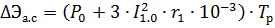
where P0 is the open-rotor power determined by the meter or wattmeter, kW; I1.o — open-rotor stator current determined by the motor ammeter, A.
For all motors, except asynchronous with a phase rotor, steel losses should not be separated as an independent element in the electrical balance due to the complexity of such a choice. Since the losses in the steel of the engine depend little on its load, as well as on the mechanical losses, it is advisable to determine them only in general with the latter.
Mechanical losses ΔEmech (kW • h) in the unit and electrical losses in the steel of the reduced motor

For DC machines

where Px.x is the idle power of the engine connected to the mechanism, determined by the counter or wattmeter, kW; Ixx-motor idling current determined by the motor ammeter, A.
Since for wound-rotor induction motors, the steel losses are determined by the formula given earlier, the mechanical losses can be distinguished using the penultimate formula.
For DC machines, steel losses are a small fraction compared to mechanical losses. Given that on the motor shaft, in addition to its own losses, there are also mechanical losses of the drive mechanism, it is possible to ignore the losses in steel without much error and assume that the last formula determines the mechanical losses of the motor and mechanism .