Approximate methods for calculating heaters
 In practical calculations, they often use approximate methods for calculating heaters, based on the use of experimental data (in the form of tables or graphical dependencies), which reflect the relationship between the load current (In), temperature, cross-sectional dimensions and diameter. Graphical dependences or tabular data are obtained for certain (standard) conditions when the wire is stretched horizontally in still air at a temperature of 293 K.
The actual surface temperature Td is brought to the calculated Tp (tabular) using the plant and environment factors:
where km and kc are installation and environmental factors. For standard conditions kM = kc = 1.
The installation factor takes into account the deterioration of heat transfer in a real heater compared to the standard conditions under which the tabulated data were obtained (km ≤ 1).For a wire spiral in still air km = 0.8 ... 0.9, for a spiral on an insulating frame (rod) km = 0.7, for a spiral or wire in a heating element, electrically heated floor, soil, panel km = 0.3 … 0.4.
The environment factor accounts for the improvement in heat transfer compared to standard conditions due to the effect of the heated environment (kc ≥1). For wire coil, wire in moving air kc = 1.1 … 4.0, for heaters of protected and sealed design in still water kc = 2.5, for heaters in moving water kc = 2.8 … 3. The values of kc and km for other operating conditions are given in the reference literature.
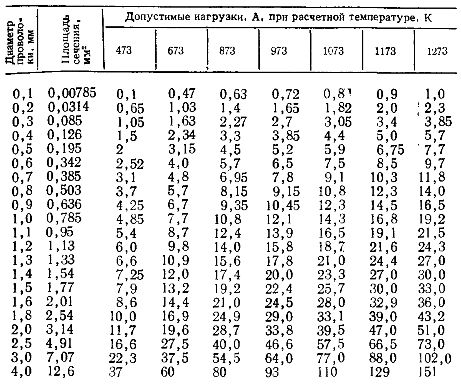
Allowable loads on nichrome wire suspended horizontally in still air at design temperature
The actual temperature of the resistance (conductor) in open-type heaters is determined by the technological conditions of the heated medium. If the temperature of the heat transfer surface of the heater is not limited by the heated medium, then the actual temperature of the heating resistance is taken from the condition Td ≤ Tmax (Tmax is the maximum allowable temperature of the heater (conductor)).
According to the accepted scheme for connecting the heaters, the current strength of one heater is determined by the formula

where Pf is the phase power of the ETU, W, Uph is the phase voltage of the network, V, Nc is the number of parallel branches (heaters) per phase.
According to Tr and In, the cross-sectional area and diameter are determined from the reference tables.
The required length, m, of the heating wire per section (heater) is found by the expression

where ρt is the electrical resistance of the wire at the actual temperature, Ohm-m.
Of practical interest are calculation methods used in specialized enterprises in the production of hermetically sealed heaters (TEN)... The initial data for calculating the heating element are:
-
rated strength
-
heater voltage,
-
active length of its shell
-
heated environment.
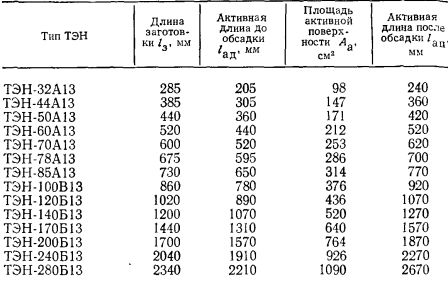
TEN shell parameters
Coil for heating elements is calculated in the following sequence:
1. According to the rated power and unfolded length according to the reference table, select the required active surface of the heater and determine the specific surface heat flux, W / cm2, on the outer surface of the heater housing:

The calculated heat flow must not exceed the maximum permissible value, i.e. Fa ≤ Fa.dop.
2. Predetermine the diameter, mm, of the heating resistance (conductor)
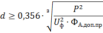
where Fa.dop.pr — permissible specific heat flow on the surface of the conductor, W / cm2. The value of FA add.pr is taken according to the reference table, depending on the working environment and the nature of the heating.
According to the reference books, the closest diameter of the wire, larger in relation to the assortment, is found.
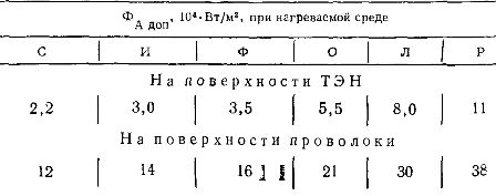
Allowable specific heat flux on the surface of the heater and the conductor
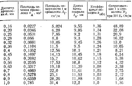
Parameters of nichrome wire (X15P60)
3. Nominal resistance, Ohm, coils at operating temperature

4. Nominal resistance, Ohm, coils at 293 K

5. Winding coil resistance
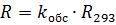
where kos is a coefficient that takes into account the change in the resistance of the conductor as a result of pressing by the sheathing method.
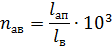
6. Active length, m, heating wire

where Rl is the electrical resistance of 1 m of wire, Ohm / m
7. Actual specific heat flow, W / cm2, on the surface of the heating wire
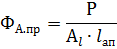
where Al is the surface area of 1 m heating wire, cm2 / m.
If Fa.pr> Fa.dop.pr, then it is necessary to increase the diameter of the wire.
8. The active number of spiral turns
where lw is the length of the helical turn, mm.
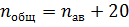
9. The total number of turns of the spiral, taking into account the necessary winding on the ends of the contact rods in the amount of 10 turns for the end of the rod
10. Pitch of the spiral, mm, before the sheathing

where lad is the active length of the heater before the housing, mm.
The calculated value of lsh is checked against the conditions:


11. Total length of spiral