Electrical insulation properties and tests
Properties and equivalent circuit of electrical insulation
As you know, the term «isolation» is used in practice to refer to two concepts:
1) a method of preventing the formation of electrical contact between parts of an electrical product,
2) materials and products from them used to apply this method.
 Electrical insulation materials under the influence of a voltage applied to them, the property of conducting an electric current is discovered. Although the value of the conductivity of electrical insulating materials is several orders of magnitude lower than that of wires, it nevertheless plays a significant role and largely determines the reliability of the operation of an electrical product.
Under the action of a voltage applied to the insulation, a current flows through it, called leakage current, which changes with time.
In order to study and illustrate the properties of electrical insulation, it is customary to represent it in the form of a certain model called an equivalent circuit (Fig. 1), containing four electrical circuits connected in parallel.The first of them contains only the capacitor C1, called geometric capacitance.
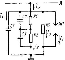
Rice. 1. Equivalent circuit of electrical isolation
The presence of this capacitance causes the appearance of an instantaneous inrush current that occurs when a DC voltage is applied to the insulation, which decays in almost a few seconds, and a capacitive current flowing through the insulation when an AC voltage is applied to it. This capacity is called geometric because it depends on the insulation: its dimensions (thickness, length, etc.) and the location between the current-carrying part A and the case (ground).
The second scheme characterizes the internal structure and properties of the insulation, including its structure, the number of groups of capacitors and resistors connected in parallel. The current I2 flowing through this circuit is called the absorption current. The initial value of this current is proportional to the area of the insulation and inversely proportional to its thickness.
If the current-carrying parts of an electrical product are insulated with two or more layers of insulation (for example, wire insulation and coil insulation), then in the equivalent circuit the absorption branch is represented in the form of two or more series-connected groups of a capacitor and a resistor that characterize the properties on one of the insulation layers. In this scheme, a two-layer insulation is considered, the layer of which is replaced by a group of elements of capacitor C2 and resistor R1, and the second by C3 and R2.
The third circuit contains a single resistor R3 and characterizes the isolation loss when a DC voltage is applied to it.The resistance of this resistor, also called insulation resistance, depends on many factors: size, material, construction, temperature, insulation condition, including moisture and dirt on its surface, and applied voltage.
With some insulation defects (for example, through damage), the dependence of the resistance R3 on the voltage becomes nonlinear, while for others, for example, with strong moisture, it practically does not change with increasing voltage. The current I3 flowing through this branch is called the forward current.
The fourth circuit is represented in the equivalent circuit of the MF spark gap, which characterizes the dielectric strength of the insulation, numerically expressed by the value of the voltage at which the insulating material loses its insulating properties and breaks down under the action of the current I4 passing through it.
This isolation equivalent circuit allows not only to describe the processes taking place in it when a voltage is applied, but also to set parameters that can be observed to assess its state.
Electrical insulation test methods
The simplest and most common way to assess the condition of the insulation and its integrity is to measure its resistance using a megohmmeter.
Let's pay attention to the fact that the presence of capacitors in the equivalent circuit also explains the ability of insulation to accumulate electric charges. Therefore, the windings of electrical machines and transformers before and after measuring the insulation resistance must be discharged by grounding the terminal to which connected megohmmeter.
When measuring the insulation resistance of electrical machines and transformers, the temperature of the windings must be monitored, which is recorded in the test report. Knowing the temperature at which the measurements were made is necessary to compare the measurement results with each other, because the insulation resistance changes sharply depending on the temperature: on average, the insulation resistance decreases by 1.5 times with an increase in temperature every 10 ° C and also increases with the corresponding decrease in temperature.
Due to the fact that moisture, which is always contained in insulating materials, affects the measurement results, the determination of parameters characterizing the quality of the insulation is not carried out at temperatures below + 10 ° C, since the results obtained will not give a correct idea of the true state of isolation.
When measuring the insulation resistance of a practically cold product, the insulation temperature can be assumed equal to the ambient temperature. In all other cases, the temperature of the insulation is conditionally assumed to be equal to the temperature of the windings, measured by their active resistance.
So that the measured insulation resistance does not differ significantly from the true value, the own insulation resistance of the elements of the measuring circuit — wires, insulators, etc. — should introduce a minimum error into the measurement result.Therefore, when measuring the insulation resistance of electrical devices with a voltage of up to 1000 V, the resistance of these elements must be at least 100 megohms, and when measuring the insulation resistance of power transformers - not less than the measurement limit of the megohmmeter.
If this condition is not met, the measurement results must be corrected for the insulation resistance of the circuit elements. To do this, the insulation resistance is measured twice: once with a fully assembled circuit and the product connected, and the second time with the product disconnected. The result of the first measurement will give the equivalent insulation resistance of the circuit and the product Re, and the result of the second measurement will give the resistance of the elements of the measuring circuit Rc. Then the insulation resistance of the product

If for electrical machines of some other products the sequence of measuring the insulation resistance is not established, then for power transformers this measurement sequence is regulated by the standard according to which the insulation resistance of the low voltage winding (LV) is measured first. The remaining windings, as well as the tank, must be grounded. In the absence of a tank, the transformer casing or its skeleton must be earthed.
In the presence of three voltage windings — lower voltage, medium high voltage and higher voltage — after the low voltage winding, it is necessary to measure the insulation resistance of the medium voltage winding and only then the higher voltage.Naturally, for all measurements, the remaining coils, as well as the tank, must be grounded, and the ungrounded coil must be discharged after each measurement by connecting to the box for at least 2 minutes. If the results of the measurements do not meet the established requirements, then the tests must be supplemented by determining the insulation resistance of the windings electrically connected to each other.
For two-winding transformers, the resistance of the high and low voltage windings should be measured relative to the case, and for three-winding transformers, the high and medium voltage windings should be measured first, then the high, medium and low voltage windings.
When testing the insulation of a transformer, it is necessary to make several measurements to determine not only the values of the equivalent insulation resistance, but also to compare the insulation resistance of the windings with other windings and the machine body.
The insulation resistance of electrical machines is usually measured with interconnected phase windings, and at the installation site — together with cables (busbars). If the measurement results do not meet the established requirements, then the insulation resistance of each phase winding and, if necessary, each branch of the winding is measured.
It should be borne in mind that it is difficult to reasonably judge the condition of the insulation by the absolute value of the insulation resistance alone. Therefore, in order to evaluate the state of insulation of electrical machines during operation, the results of these measurements are compared with the results of the previous ones.
Significant, several times, discrepancies between the insulation resistances of individual phases usually indicate some significant defect. A simultaneous decrease in insulation resistance for all phase windings, as a rule, indicates a change in the general state of its surface.
When comparing the measurement results, the dependence of the insulation resistance on temperature should be remembered. Therefore, it is possible to compare with each other the results of measurements carried out at the same or similar temperature.
When the voltage applied to the insulation is constant, the total current Ii (see Fig. 1) flowing through it decreases the more, the better the condition of the insulation, and in accordance with the decrease in the current Ii, the readings of the megohmmeter increase. Due to the fact that the I2 component of this current, also called the absorption current, unlike the I3 component, does not depend on the condition of the insulating surface, as well as on contamination and moisture content, the ratio of the insulation resistance values at given moments of time is takes as a characteristic of insulating moisture content.
The standards recommend measuring the insulation resistance after 15 s (R15) and after 60 s (R60) after connecting the megohmmeter, and the ratio of these resistances ka = R60 / R15 is called the absorption coefficient.
With non-moist insulation, ka> 2, and with moist insulation — ka ≈1.
Since the value of the absorption coefficient is practically independent of the size of the electrical machine and various random factors, it can be normalized: ka ≥ 1.3 at 20 ° C.
The error in the measurement of insulation resistance should not exceed ± 20%, unless specifically established for a specific product.
In electrical products, electrical strength tests subject the insulation of the windings to the body and to each other, as well as to the intermediate insulation of the windings.
In order to check the dielectric strength of the insulation of coils or current-carrying parts to the housing, an increased sinusoidal voltage with a frequency of 50 Hz is applied to the terminals of the tested coil or current-carrying parts. The voltage and the duration of its application are indicated in the technical documentation for each specific product.
When testing the dielectric strength of the insulation of windings and live parts to the body, all other windings and live parts not involved in the tests must be electrically connected to the earthed body of the product. After the end of the test, the coils should be earthed to remove the residual charge.
In fig. 2 shows a diagram for testing the dielectric strength of a winding of a three-phase electric motor. The overvoltage is generated by a test installation AG containing a regulated voltage source E. The voltage is measured on the high voltage side with a photovoltaic voltmeter. An ammeter PA is used to measure the leakage current through the insulation.
The product is considered to have passed the test if there is no breakdown of the insulation or overlapping of the surface, and also if the leakage current does not exceed the value specified in the documentation for this product. Note that having an ammeter that monitors the leakage current makes it possible to use a transformer in the test setup.
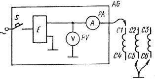
Rice. 2. Scheme for testing the dielectric strength of the insulation of electrical products
In addition to frequency voltage testing of insulation, insulation is also tested with rectified voltage. The advantage of such a test is the possibility to assess the condition of the insulation based on the results of measuring the leakage currents at different values of the test voltage.
In order to evaluate the condition of the insulation, it is used a coefficient of non-linearity
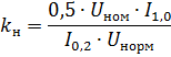
where I1.0 and I0.5 are leakage currents 1 min after the application of test voltages equal to the normalized value of Unorm and half of the rated voltage of the electrical machine Urated, kn <1.2.
The three characteristics considered — insulation resistance, absorption coefficient and nonlinearity coefficient — are used to solve the question of the possibility of turning on an electric machine without drying out the insulation.
When testing the dielectric strength of the insulation according to the diagram in fig. 2 all turns of the winding are at practically the same voltage with respect to body (ground) and therefore the turn-to-turn insulation remains unchecked.
One way to test the dielectric strength of the insulating insulation is to increase the voltage by 30% compared to the nominal. This voltage is applied from a regulated voltage source EK to the no-load test point.
Another method is applicable to generators operating at idle and consists in increasing the excitation current of the generator until the voltage (1.3 ÷ 1.5) Unom is obtained at the terminals of the stator or the armature, depending on the type of machine .Given that even in idle mode, the currents consumed by the windings of electrical machines can exceed their nominal values, the standards allow such a test to be carried out at an increased frequency of the voltage supplied to the motor windings above the nominal value or at increased generator speed.
For testing asynchronous motors, it is also possible to use a test voltage with a frequency of fi = 1.15 fn. Within the same limits, the speed of the generator can be increased.
When testing the dielectric strength of the insulation in such a manner, a voltage numerically equal to the ratio of the applied voltage divided by the number of turns of the coil will be applied between adjacent coil turns. It differs slightly (by 30-50%) from that which exists when the product operates at rated voltage.
As you know, the limit of voltage increase applied to the terminals of the coil located on the core is due to the non-linear dependence of the current in this coil on the voltage at its terminals. At voltages close to the nominal value Unom, the core is not saturated and the current depends linearly on the voltage (Fig. 3, section OA).
As the voltage increases, U above the nominal current in the coil increases sharply, and at U = 2Unom the current can exceed the nominal value by tens of times. In order to significantly increase the voltage per turn of the winding, the strength of the insulation between the turns is tested at a frequency that is many times (ten times or more) higher than the nominal one.
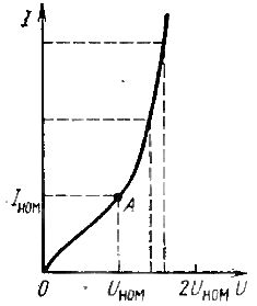
Rice. 3. Graph of the dependence of the current in the coil with a core on the applied voltage
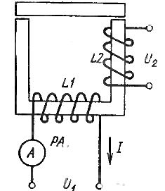
Rice. 4.Winding insulation test scheme at increased current frequency
Let's consider the principle of testing the intermediate insulation of contactor coils (Fig. 4). The test coil L2 is placed on the rod of the split magnetic circuit. A voltage U1 is applied to the terminals of the coil L1 with an increased frequency, so that for each turn of the coil L2 there is a voltage necessary to test the dielectric strength of the insulation from turn to turn. If the insulation of the windings of the coil L2 is in good condition, then the current consumed by the coil L1 and measured with the ammeter PA after the installation of the coil will be the same as before. Otherwise, the current in the coil L1 increases.
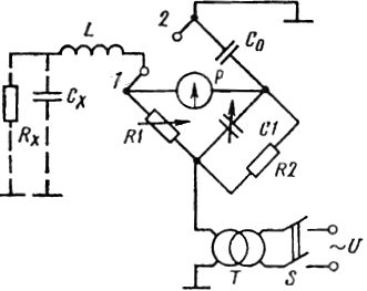
Rice. 5. Scheme for measuring the tangent of the angle of dielectric losses
The last of the considered insulation characteristics — dielectric loss tangent.
It is known that insulation has active and reactive resistance, and when a periodic voltage is applied to it, active and reactive currents flow through the insulation, that is, there are active P and reactive Q powers. The ratio P to Q is called the tangent of the dielectric loss angle and is denoted tgδ.
If we remember that P = IUcosφ and Q = IUsinφ, then we can write:
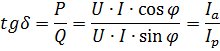
tgδ is the ratio of the active current flowing through the insulation to reactive current.
To determine tgδ, it is necessary to simultaneously measure active and reactive power or active and reactive (capacitive) insulation resistance. The principle of measuring tgδ by the second method is shown in fig. 5, where the measuring circuit is a single bridge.
The arms of the bridge are composed of an example capacitor C0, variable capacitor C1, variable R1 and constant R2 resistors, as well as the capacitance and insulation resistance of the winding L to the body of the product or mass, conventionally depicted as capacitor Cx and resistor Rx. In the event that it is necessary to measure tgδ not on the coil, but on the capacitor, its plates are connected directly to terminals 1 and 2 of the bridge circuit.
The diagonal of the bridge includes a galvanometer P and a power source, which in our case is a transformer T.
As in others bridge circuits the measurement process consists in obtaining the minimum readings of the device P by sequentially changing the resistance of the resistor R1 and the capacitance of the capacitor C1. Usually, the parameters of the bridge are chosen so that the value of tgδ at zero or minimum readings of the device P is read directly on the scale of the capacitor C1.
The definition of tgδ is mandatory for power capacitors and transformers, high voltage insulators and other electrical products.
Due to the fact that dielectric strength tests and tgδ measurements are performed, as a rule, at voltages above 1000 V, all general and special safety measures must be observed.
Electrical insulation test procedure
The parameters and characteristics of the insulation discussed above must be determined in the sequence established by the standards for specific types of products.
For example, in power transformers, the insulation resistance is first determined and then the dielectric loss tangent is measured.
For rotating electrical machines, after measuring the insulation resistance before testing its dielectric strength, it is necessary to carry out the following tests: at increased rotation frequency, with a short-term current or torque overload, with a sudden short circuit (if it is intended for this synchronous machine), insulation test of the rectified voltage of the windings (if specified in the documentation for this machine).
Standards or specifications for specific machine types may supplement this list with other tests that may affect the dielectric strength of the insulation.