Resistance, Conductance and Equivalent Circuits of Power Lines
 Power lines have active and inductive resistance and active and capacitive conductance evenly distributed along their length.
In practical electrical calculations of power transmission networks, it is customary to replace uniformly distributed DC lines with constants in combination: active r and inductive x resistance and active g and capacitive b conductivity. The equivalent circuit of a U-shaped line corresponding to this condition is shown in Fig. 1, a.
When calculating local power transmission networks with a voltage of 35 kV and below the conductivity g and b, you can ignore and use a simpler equivalent circuit consisting of series-connected active and inductive resistances (Fig. 1, b).
Linear resistance is determined by the formula

where l is the length of the wire, m; s is the cross-section of the wire or cable core, mmg γ is the specific design conductivity of the material, m / ohm-mm2.
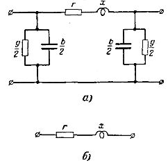
Rice. 1. Line replacement schemes: a — for regional power transmission networks; b — for local power transmission networks.
The average calculated value of the specific conductivity at a temperature of 20 ° C for single-core and multi-core wires, taking into account their actual cross-section and the increase in length when twisting multi-core wires, is 53 m / ohm ∙ mm2 for copper, 32 m / ohm ∙ mm2 for aluminum.
The active resistance of steel wires is not constant. As the current through the wire increases, the surface effect increases and therefore the active resistance of the wire increases. The active resistance of steel wires is determined by experimental curves or tables, depending on the value of the current flowing through them.
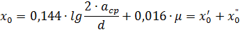
Line inductive resistance. If a three-phase current line is made with a rearrangement (transposition) of wires, then at a frequency of 50 Hz, the phase inductive resistance of 1 km of the line length can be determined by the formula
where: asr is the geometric mean distance between the axes of the wires
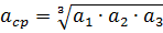
a1, a2 and a3 are the distances between the axes of the conductors of different phases, d is the outer diameter of the conductors taken according to the GOST tables for conductors; μ is the relative magnetic permeability of the metal conductor; for wires of non-ferrous metals μ = 1; x'0 — external inductive resistance of the line due to the magnetic flux outside the conductor; x «0 — internal inductive resistance of the line due to the magnetic flux that is closed inside the conductor.
Inductive resistance per line length l km

The inductive resistance x0 of overhead lines with conductors of non-ferrous metals is on average 0.33-0.42 ohms / km.
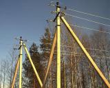
Lines with a voltage of 330-500 kV to reduce coronal losses (see below) are performed not with one core of large diameter, but with two or three steel-aluminum conductors per phase, located at a short distance from each other. In this case, the inductive resistance of the line is significantly reduced. In fig. 2 shows a similar implementation of a phase on a 500 kV line, where three conductors are located at the vertices of an equilateral triangle with sides of 40 cm. The phase conductors are fixed with several rigid striae in the section.
Using multiple wires per phase is equivalent to increasing the diameter of the wire, which leads to a decrease in the inductive resistance of the line. The latter can be calculated using the second formula, dividing the second term on its right-hand side by n and substituting instead of the outer diameter d of the wire, the equivalent diameter de determined by the formula
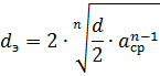
where n — the number of conductors in one phase of the line; acp — geometric mean distance between conductors of one phase.
With two wires per phase, the inductive resistance of the line decreases by about 15-20%, and with three wires - by 25-30%.
The total cross-section of the phase conductors is equal to the required design cross-section, the latter is anyway divided into two or three conductors, which is why such lines are conventionally called split-conductor lines.
Steel wires have a much larger x0 value because magnetic permeability become more than one and the second term of the second formula is decisive, that is, the internal inductive resistance x «0.
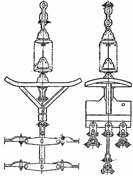
Rice. 2. 500 square meter single phase three split wire hanging garland.
Due to the dependence of the magnetic permeability of steel on the value of the current flowing through the wire, it is quite difficult to determine x «0 from steel wires. Therefore, in practical calculations, x» 0 of steel wires is determined from the curves or tables obtained experimentally.
The inductive resistances of three-core cables can be taken based on the following average values:
• for three-wire cables 35 kV — 0.12 ohms / km
• for three-wire cables 3-10 kv-0.07-0.03 ohms / km
• for three-wire cables up to 1 kV-0.06-0.07 ohms / km
An active conduction line is defined by the loss of active power in its dielectrics.
In overhead lines of all voltages, losses through insulators are small even in areas with highly polluted air, so they are not taken into account.
In overhead lines with a voltage of 110 kV and above, under certain conditions, corona appears on the wires, due to the intense ionization of the air surrounding the wire and accompanied by a violet glow and a characteristic crackle. The wire crown is especially intense in wet weather. The most radical means of reducing power losses to the corona is to increase the diameter of the conductor, because as the latter increases, the strength of the electric field and, therefore, the ionization of the air near the conductor decreases.
For 110 kV lines, the diameter of the conductor from the corona conditions should be at least 10-11 mm (conductors AC-50 and M-70), for 154 kV lines - at least 14 mm (conductor AC-95), and for 220 kV line — not less than 22 mm (conductor AC -240).
Active power losses for corona in conductors of 110-220 kV overhead lines of the specified and large conductor diameter are insignificant (tens of kilowatts per 1 km of line length), therefore they are not taken into account in the calculations.
In 330 and 500 kV lines, two or three conductors per phase are used, which, as mentioned earlier, is equivalent to an increase in the diameter of the conductor, as a result of which the strength of the electric field near the conductors is significantly reduced, and the conductors have corroded slightly.
In cable lines of 35 kV and below, the power losses in the dielectrics are small and are also not taken into account. In cable lines with a voltage of 110 kV and more, dielectric losses amount to several kilowatts per 1 km of length.
Capacitive conduction of the line due to capacitance between conductors and between conductors and ground.
With an accuracy sufficient for practical calculations, the capacitive conductance of a three-phase overhead line can be determined by the formula
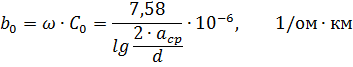
where C0 is the working capacity of the line; ω — angular frequency of alternating current; acp and d — see above.
In this case, the conductivity of the soil and the depth of current return to the ground are not taken into account, and it is assumed that the conductors are rearranged along the line.
For cables, the working capacity is determined according to the factory data.
Linear conductivity l km

The presence of capacitance in the line causes capacitive currents to flow. Capacitive currents are 90° ahead of the corresponding phase voltages.
In real lines with constant capacitive currents uniformly distributed along the length, the capacitive currents are not uniform along the length of the line because the voltage across the line is not constant in magnitude.
Capacitive current at the beginning of the line accepting a DC voltage
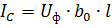
where Uph is the line phase voltage.
Capacitive line power (power generated by the line)

where U is the phase-to-phase voltage, sq.
From the third formula it follows that the capacitive conductivity of the line depends little on the distance between the conductors and the diameter of the conductors. The power generated by the line is highly dependent on the line voltage. For overhead lines 35 kV and below it is very small. For a 110 kV line with a length of 100 km, Qc≈3 Mvar. For a 220 kV line with a length of 100 km, Qc≈13 Mvar. Having split wires increases the line capacity.
Capacitive currents of cable networks are taken into account only at voltages of 20 kV and above.