Electric contact heaters
 Electric contact heating by resistance is used for heating, contact welding, lamination in the restoration of worn parts and heating pipelines.
By heating, it is used as the main method of heating parts and details for their subsequent pressure treatment or heat treatment, as well as as an integral part of technological heating in combination with other operations in the production of semi-finished or finished parts. By heating, electrical energy is converted into thermal energy directly in parts or details included in the electrical circuit. Both direct and alternating current can generally be used for heating.
In electrical contact installations, alternating current is widely used, since the currents required for heating in the thousands and tens of thousands of amperes at a voltage of several volts can most easily be obtained only with the help of alternating current transformers. Installations for electric contact heating of parts or details are divided into single-position and multi-position (Fig. 1).
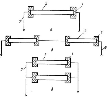
Rice. 1. Schemes of single-position (a) and multi-position devices with serial (b) and parallel (c) inclusion of details in an electrical circuit: 1-clamping contact for current current; 2 — heated detail; 3 — current supply wire.
Depending on the required heating rate and the productivity of the technological line, one or another scheme is used. For technical and economic reasons, it is most advantageous to use a myoposition scheme with a series connection of the heated workpieces to the electrical circuit, since in this case any given speed of delivery of the heated workpieces is ensured by a gradual increase in their temperature to a predetermined value by moving the details from one position to another.
Regardless of the scheme for including the heated parts in the electrical circuit, the current load at the points of contact of the current-carrying contacts with the heated workpiece has a great influence on the technological, electrical and technical and economic indicators of electrical contact installations. Current loading is reduced by cooling and pressurizing the contacts, as well as by using clamps with radial and end contacts.
Single-phase and three-phase electrical contact installations can be used in repair enterprises. Three-phase installations are more efficient than single-position single-phase installations of the same performance, as they provide an even load on the phases of the supply network and reduce the current load on each phase.
The option of electric contact heating and heating installation is selected depending on the specific conditions.
The main electrical characteristics of electric contact heating installations
The following design parameters are determined for each electrical contact installation:
-
power transformer power,
-
the required electric current in the secondary circuit,
-
stress on the heated part or workpiece,
-
efficiency
-
Power factor.
The initial data for calculating electrical contact installations are:
-
material class,
-
mass of the heated part and its geometric dimensions
-
power supply voltage,
-
heating time and temperature.
Apparent power, V ∙ A, of a power transformer for a single-position device:
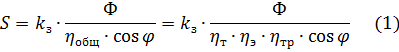
where kz = 1.1 ...1.3 — safety factor; F — useful heat flow; ηtotal — overall efficiency of the installation: ηe — electrical efficiency; ηt — thermal efficiency; ηtr — power transformer efficiency.
Current strength, A, in the secondary circuit when the workpiece is heated to a temperature above the magnetic conversion point
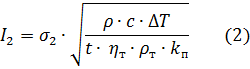
where ρ is the density of the material of the workpiece, kg / m3; ΔT = T2 — T1 is the difference between the final T2 and the initial T1 temperature of the workpiece heating, K; σ2 - cross-sectional area of the workpiece, m2.
The heating time depends on the diameter of the workpiece and the temperature difference along the length and cross section. According to the technological conditions, the temperature difference between the internal and surface layers of the heated workpiece should not exceed ΔТП = 100 K. The calculated and experimental graphical dependences for determining the heating time are given in the reference literature.
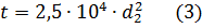
In practical calculations, the heating time, s, of cylindrical blanks with a diameter of d2 = 0.02 … 0, l m s ΔTP = 100 K can be determined by the empirical formula
If the workpiece is heated to a temperature below the magnetic conversion point, then when determining the current in the secondary circuit, it is necessary to take into account the surface effect, the degree of influence of which depends on the magnetic permeability.
With respect to electric contact heating, the empirical dependence establishing the relationship between the current I2, the relative magnetic permeability μr2 of the workpiece and its diameter has the form
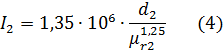
In practical calculations, they are usually given with different values of μr2, and the current strength I2 is determined by the formulas. The same amperage value found from the given formulas (2) and (4) will be the desired value at a given point in time. According to the calculated values of I2 and Z2, the voltage, V, in the secondary circuit is given by the expression
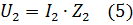
Rice. 2. Dependence of cosφ of electrical contact installations on the ratio l2 / σ2: 1 — for a two-position installation with variable heating of two blanks; 2 — for two-position installation with simultaneous heating of two stocks; 3 — for one-position installation.
When determining the main electrical characteristics of an electrical contact installation, it is necessary to take into account that the physical parameters of the part and the electrical parameters of the installation change during the heating process. The specific heat cm and the specific electrical resistance of the conductor ρт change depending on the temperature, and cosφ, η and t — depending on the temperature, the construction and technological type of installation and the number of heating positions.
According to the graphical experimental dependences (Fig. 2, 3), cosφ and ηtotal are determined depending on the ratio of the length of the workpiece l2 to σ2. The required values of S, l2 and U2 can be obtained by substituting the corresponding values of the variable quantities in formulas (1), (2), (4) and (5). In practical calculations, the average values of cm, ρt, η, t and cosφ are usually substituted into the formulas and the average value of power, current or voltage is determined over the assumed heating temperature interval.
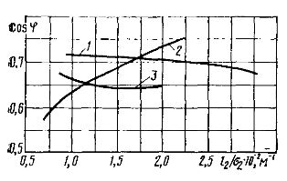
Rice. 3. Dependence of the overall efficiency of electrocontact installations on the l2 / σ2 ratio: 1 — for a two-position installation with variable heating of two workpieces; 2 — for two-position installation with simultaneous heating of two workpieces; 3 — for one-position installation.
The power transformers of electrical contact installations work in a periodic mode, which is characterized by the relative duration of switching on
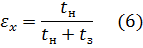
where tn is the time for heating the blanks, s; t3 — time of cargo-unloading and transport operations, sec.
The total rated power, kVA, of a power transformer, taking into account εx, is determined by the expression
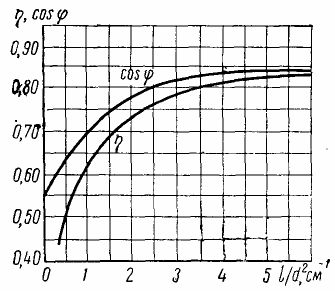
Rice. 4. Dependence of the efficiency and power factor of an electric contact heating installation on the dimensions of the part