Internal power supply schemes for enterprises for 6-10 and 35-110 kV
 The internal power supply scheme of the enterprise is developed taking into account the location of energy sources and consumers, the values of their voltages and powers, the required reliability, the location and design of lines, distribution substations and workshop transformer substations, as well as the requirements for the power supply system .
The reliability or economy of the scheme is increased if the following conditions are met:
a) the number of transformation stages is reduced and the source of higher voltage is closer to the user,
b) special backup (usually non-working) lines and transformers are not provided, all elements of the circuit in normal mode must be under load and work separately, in case of an accident of one of the elements (line, transformer), the rest can work with permissible overload, predicted by PUE, and with the exclusion of some of the irresponsible users.
c) in all connections of the power distribution system, starting from the busbars of the gas transmission system and ending with busbars for voltages up to 1000 V from the TP workshop, and sometimes from the RP power workshop, sectioning of the bus is carried out, and if the loads of the first and second category, automatic transfer switch (ATS) is provided,
d) the parallel operation of lines and transformers is provided for shock-abruptly variable loads (roller mills, powerful welding units, electric furnaces) or when the automatic transfer switch does not provide the necessary speed of power recovery determined by the mode of energy consumers. The parallel work option is accepted only with a feasibility study.
Electricity at voltages of 6-10 kV is distributed according to the radial and trunk circuits.
Radial circuits (single-stage and two-stage) are used when placing consumers in different directions from the power source.
In small plants and for the delivery of large concentrated loads, single-stage schemes are used. Two-level schemes with intermediate RPs are implemented for large and medium-sized enterprises with workshops located on a large territory. The transformers of commercial TPs and large electrical receivers are powered by the intermediate RP. The transformers of the TP shop are tightly connected to the lines and all the switching equipment is installed on the RP. Typically four to five TPs are connected to one RP.
Radial chains of more than two stages make the line of head sections heavier, complicate protection and switching.
In the presence of electrical receivers of the first and second category, RP and substations are fed by at least two separately operating lines. If third-category receivers predominate in the workshop, then it is powered by a substation with one transformer, and the power supply of individual critical loads is preserved by jumpers between substations.
A radial scheme with an intermediate RP in which the above conditions are met is shown in Fig. 1.
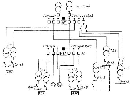
Rice. 1. Diagram of radial feed of the enterprise
RP, TP1, TP4, TP5 and TP6 are fed along the radial lines of the first stage. TP2 and TP3 are fed through the lines of the second stage. All switching devices are located on GPP and RP. Two transformers are installed at TP1, TP2 and TPZ, each with a dead connection to the supply lines. Each line and transformer is designed to cover all loads of the first category and the main loads of the second category. In the absence of data on the nature of the loads, each line and transformer of two-transformer substations is selected on the basis of 60-70% of the total load of the substation .
Buses GPP, RP, TP1, TP2 and TPZ are separated (deep separation principle). Sectional units are usually open and have an ATS unit provided on them. In case of failure of any element (line or transformer), it is switched off, the ATS device of the sectional device is activated, which, when switched on, provides power to consumers through a parallel element of the circuit, using its overload capacity.
One transformer is installed on TP4, TP5 and TP6. To power the receivers of the second category, a jumper is made between TP4 and TP5 on the 0.4 kV side.The throughput of low-voltage jumpers, cable or busbars (in the case of a transformer-bus block diagram), between substations, if necessary under the conditions of reliability, is taken as 15-30% of the transformer capacity.
Electrical receivers of the second category do not require special redundancy and therefore can be powered from a single source. However, the interruption of the power supply leads to production losses or damages caused by the cost of labor downtime, disruption of the technological process, product shortages, etc.
In industrial enterprises, the majority of receivers of the second category, and some of them in their characteristics are close to the electrical receivers of the first category, and some of the third. Taking into account the degree of reliability of the individual elements of the power system, the PUE provides for powering the receivers of the second category either through a single overhead line or current wire, or through a cable line divided into two cables.
If one of the cables is damaged, the circuit breaker turns off the entire line, the personnel disconnects the damaged cable from both sides with the disconnector and turns on the circuit breaker. All the load is transferred to the working cable.
Radial schemes are used for cable or overhead lines. Trunk circuits are used for linear ("stacked") placement of substations on the territory of the enterprise and are performed in the form of single and double trunks with one or two-way power supply.
Single highways without reserves (Fig. 2, a) are used to supply irresponsible consumers. The scheme of a single line with bidirectional power supply (Fig. 2, b) is more reliable.In normal mode, the substations can be powered from only one source (with the second one as backup) or from two sources at the same time, while the trunk is open on one of the substations. A special case of a single line with bidirectional power supply is a ring circuit (Fig. 2, c).
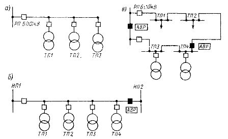
Rice. 2. Schemes of single highways: a — power from a single source, b — with bidirectional power, c — ring
Two-line circuits are highly reliable and are used in the presence of loads of the first and second category in substations with two bus sections (Fig. 3, a) or in two-transformer substations without high-voltage buses. Each rack is designed to cover the load of responsible users of all substations. Sectional switches are usually open and equipped with ATS. The lines can be fed from a second source. The scheme of a military line with bidirectional power supply ("opposite" line) is used in the presence of two independent sources (Fig. 3, b).
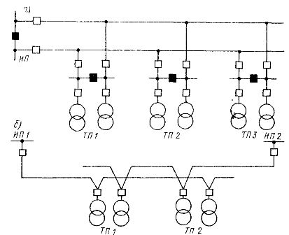
Rice. 3. Diagrams of pass-through networks: a — double through the network in the presence of high-voltage buses in workshop substations, b — with two-way supply in the absence of high-voltage buses in workshop substations
Structurally, trunk circuits are made with cables, wires and overhead lines. For 6-10 kV cable lines, it is recommended to connect no more than four to five transformers with a capacity of 1000 kVA to one trunk. Busbar circuits are recommended in case of concentrated power users and transmission of smaller energy flows.
Main overhead lines connect individual gas transmission stations at a voltage of 35-220 kV and feed PGV.Deep entries are made in the form of main overhead lines with branch taps to substations 35-220 kV or in the form of radial cables and overhead lines. The deep sleeve allows power distribution at increased voltage, shortens the length of 6-10 kV cable lines, makes it possible to do without intermediate 6-10 kV substations, destroys powerful GPPs, facilitates voltage regulation and simplifies the development of power supply system.
Internal power supply schemes for electrical receivers of the first category
For receivers of the first reliability category, an interruption in the power supply is permissible only for the time of the automatic introduction of a backup power supply, and the power supply must be carried out by two independent power sources. An independent power source PUE is considered a source on which the voltage is maintained when it disappears from other sources.
Independent sources include the switchgear of two power plants or substations, as well as two sections of distribution busbars (RU) that are not electrically connected to each other either at the receiving point or through the supply network (Fig. 4).
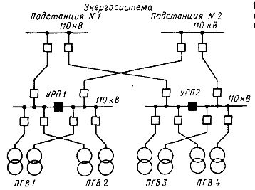
Rice. 4. Powering a large enterprise from two independent sources
The deep separation of all connections of the system with ATS devices on sectional switches ensures reliability and uninterrupted power supply to consumers of the first category.
Electrical receivers of a special group of the first category require increased reliability of the power supply. They must be powered by three independent sources, so that when one of them is repaired, power is supplied from the other two.In the supply circuits, this condition is fulfilled by spare cable jumpers from neighboring substations (Fig. 5) or by special diesel generator sets.
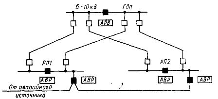
Rice. 5. Example of a power supply scheme when powering a special group of electricity consumers
Cable jumpers (and the capacity of the third emergency source) are selected based on the load of a special group of receivers, designed only for trouble-free shutdown of production.
With a small power of receivers of a special group, it is possible to provide uninterruptible power supply units (UPS) with a capacity of 16-260 kVA with rechargeable batteries.
See also on this topic (good quality diagrams):