Voltage regulation devices in industrial networks
 In order to choose means of voltage regulation and their placement in the power supply system, it is necessary to identify the voltage levels at its various points, taking into account the powers transmitted through its individual sections, the technical parameters of these sections, the cross section of the lines, the power of the transformers, the types of reactors, etc. regulations are based not only on technical but also on economic criteria.
The main technical means of voltage regulation in power supply systems of industrial enterprises are:
-
power transformers with load control devices (OLTC),
-
step-up transformers with load regulation,
-
capacitor banks with longitudinal and transverse connection, synchronous motors with automatic regulation of the excitation current,
-
static sources of reactive power,
-
local power plant generators found in most large industrial plants.
In fig.1 shows a diagram of centralized voltage regulation in the distribution network of an industrial enterprise, it is carried out by a transformer with an automatic voltage regulation device under load... The transformer is installed at the main step-down substation (GPP) of the enterprise. Transformers with load switches, are equipped with automatic load voltage regulation (AVR) units.
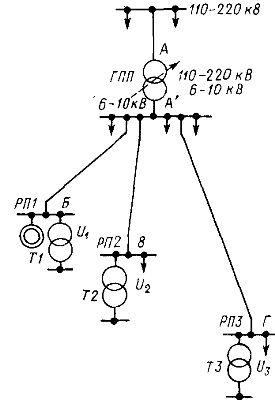
Rice. 1. Scheme for centralized voltage regulation in the distribution network of an industrial enterprise
Centralized voltage regulation in some cases turns out to be insufficient. Therefore, for electrical receivers that are sensitive to voltage deviations, they are installed in the distribution network step-up transformers or individual voltage stabilizers.
Working transformers of distribution networks, transformers T1 — TZ (see Fig. 1), as a rule, do not have devices for regulating the load voltage and are equipped with control devices without excitation, type PBV, which allow switching the branches of the power transformer when is disconnected from the network. These devices are generally used for seasonal voltage regulation.
An important element that improves the voltage regime in the network of an industrial enterprise is reactive power compensation devices — capacitor batteries with transverse and longitudinal connection. The installation of capacitors connected in series (UPC) makes it possible to reduce inductive resistance and voltage loss in the line.For UPK, the ratio of the capacitive resistance of the capacitors xk to the inductive resistance of the line xl is called the compensation percentage: C = (xc / chl) x 100 [%].
UPC devices parametrically, depending on the magnitude and phase of the load current, adjust the voltage in the network. In practice, only partial compensation of line reactance (C < 100%) is resorted to.
Full compensation in case of sudden load changes and in emergency modes can cause surges. In this regard, at significant values of C, UPK devices must be equipped with switches that bypass part of the batteries.
For power supply systems, CCPs are being developed with shunting of part of the battery sections with thyristor switches, which will expand the scope of CCPs in the power supply systems of industrial enterprises.
Capacitors connected in parallel with the network generate x reactive power and voltage simultaneously as they reduce network losses. Reactive power generated by similar batteries — lateral compensation devices, Qk = U22πfC. Thus, the reactive power delivered by the bank of cross-connected capacitors depends largely on the voltage across its terminals.
When choosing the power of the capacitors, it is based on the need to ensure a voltage deviation that corresponds to the norms at the calculated value of the active load, which is determined by the difference in linear losses before and after switching on the capacitors:
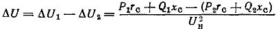
where P1, Q2, P2, Q2 are active and reactive powers transmitted on the line before and after the installation of capacitors, rs, xc — network resistance.
Considering the invariance of the active power transmitted along the line (P1 = P2), we have:
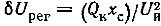
The regulating effect of connecting a capacitor bank in parallel to the network is proportional to xc, i.e. the voltage increase in the user at the end of the line is greater than at its beginning.
The main means of voltage regulation in the distribution networks of industrial enterprises are load-controlled transformers... The control taps of such transformers are located on the high-voltage winding. The switch is usually placed in a common tank with a magnetic circuit and driven by an electric motor. The actuator is equipped with limit switches that open the electrical circuit to supply the motor when the switch reaches the limit position.
In fig. 2, a shows a diagram of a multilevel switch of the RNT-9 type, which has eight positions and a depth of adjustment of ± 10%. The transition between stages is accomplished by maneuvering adjacent stages to the reactor.
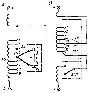
Rice. 2. Switching devices of power transformers: a — switch of the RNT type, R — reactor, RO — regulating part of the winding, PC — movable contacts of the switch, b — switch of the RNTA type, TC — current limiting resistance, PGR switch for coarse adjustment, PTR — fine tuning switch
The native industry also manufactures RNTA series switches with active current limiting resistance with smaller adjustment steps of 1.5% each. Shown in fig. 2b, the RNTA switch has seven fine tuning steps (PTR) and a coarse tuning step (PGR).
Currently, the electrical industry also produces static switches for power transformers, enabling high-speed voltage regulation in industrial networks.
In fig. 3 shows one of the power transformer disconnection systems mastered by the electrical industry — a "through resistor" switch.
The figure shows the control area of the transformer, which has eight taps connected to its output terminal by means of bipolar groups VS1-VS8. In addition to these groups, there is a bipolar thyristor switching group connected in series with the current limiter R.
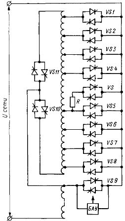
Rice. 3. Static switch with current limiter
The principle of operation of the switch is as follows: when switching from tap to tap, in order to avoid a short circuit of the section or an open circuit, the output bipolar group is completely extinguished by transferring the current to the tap with a resistor, and then the current is transferred to the required faucet. For example, when switching from faucet VS3 to VS4, the following cycle occurs: VS turns on.
The short circuit current of the section is limited by the current limiting resistor R, thyristors VS3 are off, VS4 is on, thyristors VS are off. Other commutations are done in the same way. Bipolar thyristor groups VS10 and VS11 reverse the regulatory zone. The switch has a strengthened thyristor block VS9, which realizes the zero position of the regulator.
A feature of the switch is the presence of an automatic control unit (ACU), which issues control commands to VS9 in the interval when the transformer is turned on at idle.BAU works for some time, it takes the sources feeding thyristor groups VS1 — VS11 and VS to enter mode, since the transformer itself serves as a power supply for the switch control system.