Measures and technical means to improve the quality of electrical energy
 To keep voltage deviations and fluctuations within standards-compliant values, voltage regulation is required.
Voltage regulation is a process of changing the voltage levels at characteristic points of the power supply system with the help of special technical means, which is carried out automatically according to a predetermined law. The voltage regulation law in power centers (CPU) is determined by the power supply organization, taking into account the interests of the majority of users connected to that CPU, if possible.
In order to ensure the necessary voltage regime at the terminals of electrical energy receivers, the following methods of voltage regulation are used: in the buses of power plants and substations (CPU), on outgoing lines, joint and additional.
When regulating the voltage on the processor buses, they provide the so-called countercurrent regulation.Counter voltage regulation is understood as increasing the voltage to 5 - 8% of nominal at the highest load and under voltage to nominal (or lower) at the lowest load with a ramp depending on the load.
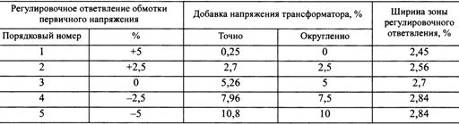
Regulation is done by changing the transformation ratio of the supply transformer… For this purpose, transformers are equipped with on-load voltage regulation means (OLTC)… Transformers with on-load switches allow voltage regulation in the range of ± 10 to ± 16% with resolution 1.25 — 2.5%. Power transformers 6 — 20 / 0.4 kV equipment switch control devices of the off-circuit switch (switching without excitation) with a range of ± 5% and an adjustment step of ± 2.5% (Table 1).
Table 1. Voltage allowances for 6-20 / 0.4 kV transformers with circuit breaker
Right choice transformation factor a transformer with a circuit breaker (for example with seasonal regulation) provides the best possible voltage regime when the load changes.
The expediency of using one or another method of voltage regulation is determined by local conditions, depending on the length of the network and its circuit, reactive power reserve, etc.
The voltage deviation indicator depends on the voltage loss in the network, depends on the resistance of the network and the load.In practice, the change in the resistance of the network is associated with a change in the voltage in it when choosing the cross-sections of wires and cable cores, taking into account the deviations in the voltage of the receivers of electric power (according to the permissible voltage losses), as well as when using of series connection of capacitors in overhead lines (longitudinal compensation installations — UPK).
Capacitors connected in series compensate for some of the inductive resistance of the line, thus reducing the reactive component in the line and creating some additional voltage in the network, depending on the load.
Series connection of capacitors is recommended only for significant load reactive power (tgφ > 0.75-1.0). If the reactive power factor is close to zero, line voltage loss are mainly determined by active resistance and active power. In these cases, inductive resistance compensation is impractical.
The use of UPC is very effective in the case of sharp fluctuations in the load, because the regulating effect of the capacitors (the value of the added voltage) is proportional to the load current and changes automatically with practically no inertia. Therefore, series connection of capacitors should be used in overhead lines of voltage 35 kV and below, supplying suddenly alternating loads with relatively low power factor. They are also used in industrial networks with sharply fluctuating loads.
In addition to the measures discussed above to reduce network resistance, measures to change network loads, especially reactive ones, lead to a reduction in voltage losses and therefore to an increase in end-of-line voltage. This can be done by applying lateral compensation installations (connecting capacitor banks in parallel with the load) and high-speed reactive power sources (RPS), developing the actual schedule of reactive power changes.
In order to improve the network voltage regime, to reduce voltage deviations and fluctuations, it is possible to use powerful synchronous motors with automatic excitation control.
To improve such power quality indicators it is recommended to connect electrical receivers that distort CE at the system points with the highest short-circuit power values. And the use of means for limiting short-circuit currents in networks containing specific loads should be carried out only within the limits necessary to ensure reliable operation of switching devices and electrical equipment.
The main ways to reduce the influence of non-sinusoidal voltage. Among the technical means are used: filter devices: switching in parallel with the load of narrow-band resonant filters, filter-compensating devices (FCD), filter balancing devices (FSU), IRM containing FCD, special equipment characterized by a low level of generation of higher harmonics, "unsaturated" transformers, multiphase converters with improved energy characteristics.
In fig.1, a shows a diagram of a transverse (parallel) passive filter with higher harmonics. A filter connection is a circuit of inductance and capacitance connected in series, tuned to the frequency of a particular harmonic.
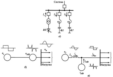
Rice. 1. Schematic diagrams of filters with higher harmonics: a — passive, b — active filter (AF) as a voltage source, c — AF as a current source, VP — valve converter, F5, F7 — respectively filter connections to 5 7th and 7th harmonics, tis — line voltage, tiAF — AF voltage, tin — load voltage, Azc — line current, AzAf — current generated by AF, Azn — load current
Resistance of the filter connection to higher harmonic currents Xfp = XLn-NS° C/n, where XL, Xc are the resistances of the reactor and the capacitor bank respectively to the power frequency current, n — the number of the harmonic component.
As the frequency increases, the reactor inductance increases proportionally and the capacitor bank decreases inversely with the harmonic number. At the frequency of one of the harmonics, the inductive resistance of the reactor becomes equal to the capacitance of the capacitor bank and voltage resonance... In this case, the resistance of the filter connection n the resonant frequency current is zero and it maneuvers the electrical system at this frequency. The harmonic number yar of the resonance frequency is calculated by the formula

An ideal filter completely filters harmonic currents to the frequencies to which its connections are tuned.In practice, however, the presence of active resistances on reactors and capacitor banks and inaccurate tuning of the filter connections lead to incomplete filtering of harmonics. A parallel filter is a series of sections, each tuned to resonate for a specific harmonic frequency.
The number of links in the filter can be arbitrary. In practice, filters consisting of two or four sections tuned to the frequencies of the 5th, 7th, 11th, 13th, 23rd and 25th harmonics are usually used. Transverse filters are connected both at the places where the higher harmonics appear and at the points where they are amplified. The crossover filter is both a source of reactive power and a means of compensating reactive loads.
The parameters of the filter are chosen in such a way that the connections are tuned in resonance with the frequencies of the filtered harmonics, and their capacitance makes it possible to generate the necessary reactive power at the industrial frequency. In some cases, a capacitor bank is connected in parallel with the filter to compensate for reactive power. Such a device is called a compensating filter (PKU)... Filter compensating devices perform both the function of filtering harmonics and the function of reactive power compensation.
Currently, in addition to passive narrowband filters, they also use active filters (AF)... An active filter is an AC-DC converter with capacitive or inductive storage of electrical energy on the DC side, which forms a certain voltage or current value through pulse modulation. It includes integrated power switches connected according to standard schemes.The AF connection to the network as a voltage source is shown in fig. 1, b, as a current source — in fig. 1, c.
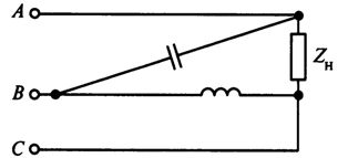
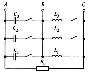
The reduction of systematic imbalance in low-voltage networks is carried out by rational distribution of single-phase loads between phases in such a way that the resistances of these loads are approximately equal to each other. If the voltage imbalance cannot be reduced using circuit solutions, then special devices are used: asymmetric switching of capacitor banks (Fig. 2) or balancing circuits (Fig. 3) of single-phase loads.
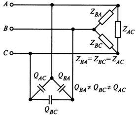
Rice. 2. Capacitor bank balancing device
Rice. 3. Special balun circuit
If the asymmetry changes according to the probability law, then automatic balancing devices are used to reduce, the diagram of one of which is shown in fig. 4. Adjustable symmetrical devices are expensive and complex and their application raises new problems (in particular non-sinusoidal voltage). Therefore, there is no positive experience with the use of baluns in Russia.
Rice. 4. Typical balun circuit
For surge protection, surge arresters... Against short-term voltage dips and voltage dips, dynamic voltage distortion compensators (DKIN) can be used, which solve many power quality problems, including dips (including impulse) and surges in supply voltage.
The main advantages of DKIN:
-
without batteries and all the problems associated with them,
-
response time for short power interruptions 2 ms,
-
the efficiency of the DKIN device is more than 99% at 50% load and more than 98.8% at 100% load,
-
low energy consumption and low operating costs,
-
compensation of harmonic components, jitter,
-
sinusoidal output voltage,
-
protection against all types of short circuits,
-
high reliability.
Reducing the level of negative impact on the network of power receivers of specific loads (shock, with non-linear volt-ampere characteristics, asymmetric) is achieved by their normalization and division of power supply into specific and "quiet" loads.
In addition to the allocation of a separate input for specific loads, other solutions are possible for the rational construction of power supply schemes:
-
four-section scheme of the main step-down substation at a voltage of 6-10 kV with transformers with split secondary windings and with double reactors for separate supply of «silent» and specific load,
-
transfer of transformers of the main step-down substation (GPP) to parallel operation by switching on a 6-10 kV sectional switch when short-circuit currents are permissible. This measure can also be applied temporarily, for example during start-up periods of large engines,
-
implementing a lighting load in the shop power networks separately from the abrupt alternating power supply (for example, from welding devices).