Placement of compensatory devices in distribution networks of enterprises
 When choosing and placing reactive power compensation means in the power supply systems of industrial enterprises, two groups of industrial networks are distinguished, depending on the composition of their loads:
-
the first group — networks of general purpose, networks with direct sequence mode of the main frequency 50 Hz,
-
the second group — networks with specific non-linear, asymmetric and sharply variable loads.
Solution of the problem reactive power compensation for the second group there are a number of characteristics, including the need to provide power quality indicators for electrical receivers with the required speed.
In the design, the largest total calculated active and reactive power enterprises Rcalc and Qcalc, which state factor of the natural power.
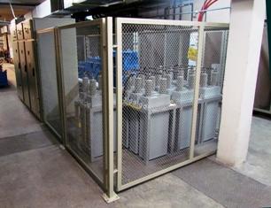
Working diagram of the compensating device
To determine the power of compensating devices, the calculated power Qcalculated is not used., and the smaller value Qswing taking into account the discrepancy in time between the highest active load of the power system and the highest reactive power of the industrial enterprise. This discrepancy is taken into account by the swing coefficient, the values of which, depending on which industry the enterprise belongs to, vary from 0.75 to 0.95. Then Qswing = swing Qcalc
The values of the highest active load Pcalc and the total reactive Qmax are taken into account in the power system to determine the value of the optimal economic reactive power that the power system can transfer to the utility in the modes of the highest and lowest active load of the power system, respectively Qe1 and Qe2.
By power QNSl is determined the total power of the compensating devices QNS = QmaNS -Qe1, and by power QNS2 — adjustable part of the compensating devices QNSreg=Qe1 — Qe2
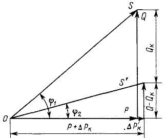
Compensating devices installed on the low-voltage buses of the main step-down substations (GSP) of the enterprise not only ensure the maintenance of the cosφsyst system power factor, but also reduce the power of the power transformers GPP Str:
Such compensating devices can be synchronous compensators, capacitor banks and synchronous motors.
Synchronous compensators are installed only in gas transmission plants of large industrial enterprises in agreement with the power supply system, while synchronous compensators are in the balance of the power system and are used when necessary (for example, in case of system failures) as a backup source of reactive power. Therefore, their installation in networks of the first group is limited.
High-voltage synchronous motors (compressor motors, pumping stations, etc.) are taken into account in the overall reactive power balance of the enterprise, but as a rule, their reactive power is not sufficient, and then the missing reactive power is filled by capacitor banks.
Reactive power balance in a 6 — 10 kV node of an industrial plant can be written as the following ratio:
Qvn + Qtp + ΔQ — Qsd — Qkb — Qe1 = 0,
where Qvn is the calculated reactive load of high-voltage receivers (HV) 6 — 10 kV, Qtp is the uncompensated load power Qn networks up to 1 kV fed by transformers of workshop transformer substations (TS), ΔQ — reactive power losses in the network 6 — 10 kV, especially in GPP transformers.
Using capacitors for voltages of 6 - 10 kV reduces the cost of reactive power compensation, since low voltage capacitors are usually more expensive (per kvar of power).
In low-voltage networks (up to 1 kV) of industrial enterprises, to which most of the receivers of electricity that consume reactive power are connected, the load power factor is in the range of 0.7 — 0.8. These networks are electrically further away from the power system feeds or the local CHP (CHP).Therefore, to reduce reactive power transmission costs, compensating devices are located directly in the network up to 1 kV.
In enterprises with specific loads (shock, sharply variable), in addition to the above-mentioned compensating devices, filter-compensating, balancing and filter-balancing devices are used in the networks of the second group. Recently, instead of rotating compensators, compensators of static reactive power (STK) are increasingly used, which, along with improving the power factor, allow you to stabilize the supply voltage.
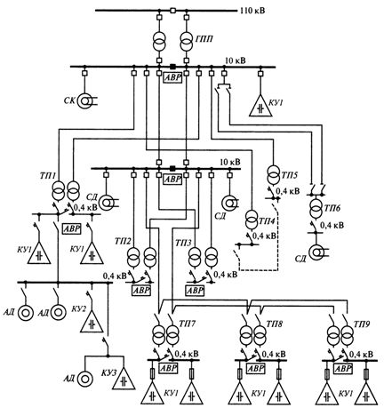
Rice. 1. Placement of compensating devices in the power supply networks of an industrial enterprise: GPP — the main step-down substation of the enterprise, SK — synchronous compensator, ATS — automatic transfer switch, KU1 — KB for centralized reactive power compensation, KU2 — KB for group compensation of reactive power, KU3 — KB for individual reactive power compensation, TP1 -TP9 — workshop transformer substations, SD — synchronous motors, AD — asynchronous motors
In the service networks of most enterprises, static capacitor banks are used for reactive power regulation. In this case, centralized (KU1), group (KU2) or individual (KU3) reactive power compensation is performed.
Thus, the sources of reactive power in the power supply system of an industrial plant used to compensate for reactive power can be located as shown in Fig. 1.