Setting up devices for automatic control
 New incoming automation equipment is usually in the form of a mohal, designed for long-term storage and transportation. Before starting the installation, these devices are unpacked, all measuring, regulating and other devices are removed and sent to the laboratory for routine inspection and verification.
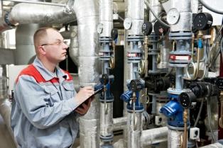
During operation, the accuracy of the readings of the measuring devices decreases due to wear of individual parts, aging and changes in the characteristics of the elements, and errors appear. To restore operational properties, the equipment periodically undergoes preventive maintenance, the purpose of which is to identify possible malfunctions and eliminate them, as well as to find weaknesses, sources of possible malfunctions, and thus prevent the occurrence of these malfunctions during operation.
After repairs caused by a violation of the rules and a change in the characteristics of devices and sensors, they must undergo an initial inspection in accordance with existing GOSTs.The results of the inspection are recorded in the protocol in the form given in the relevant methodological documents.
Based on these results, the reduced relative error of the device is determined, that is, it is determined whether it meets its accuracy class. When working with technical devices, errors are considered to correspond to their accuracy class and do not introduce changes in the readings. Correction tables are sometimes compiled for laboratory instruments.
Instruments and sensors for measuring mechanical quantities. When checking and adjusting these devices, special care and accuracy are required, since the slightest carelessness in operation (pollution, shock and overload) can lead to irreversible disturbances in the operation of the devices and to a decrease in the accuracy of their readings.
In contact displacement converters, keep the contact surfaces clean and limit the current flowing through the contacts. To limit the current strength, various electronic relays are used, and to increase the reliability of contact sensors, structures are used in which the contacts when actuated move somewhat relative to each other (rub), due to which their working surfaces are cleaned of dirt and corrosion products.
When adjusting the rheostat sensors, the pressure of the sliding contacts increases, which improves the electrical contact, but the friction increases.
When checking and adjusting inductive displacement sensors, it is necessary to take into account their sensitivity to changes in temperature and especially to changes in the frequency of the supply current.
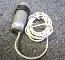
Capacitive sensors need careful shielding of the wires, since the change in the capacitance of the latter leads to noticeable errors in the operation of the sensors.
Checking temperature measuring devices.
Inspection of contact glass technical expansion thermometers includes: visual inspection, inspection of readings and consistency of readings. During an external inspection, the compliance of the thermometer with the technical requirements is established: the absence of tears in the liquid column in the capillary and traces of evaporated liquid on the walls of the latter, the operability of the movable electrode and the magnetically rotating device.
Liquid expansion thermometers are checked by comparing their readings with those of a higher grade liquid thermometer or standard. resistance thermometers.
Three types of methodological errors are characteristic of manometric thermometers: barometric, related to the instability of barometric pressure, hydrostatic, related to the height of the column of the working fluid in the system and inherent in liquid thermometers, temperature, related to the difference between the temperatures of the connecting capillary (and the manometric spring) and the thermocylinder.
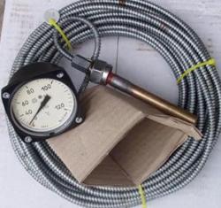
Checking manometric thermometers includes: external examination and testing, determining the main error and variation, establishing the quality of the recording and checking the chart error (for recording devices), checking the error in the operation of the signaling device for signaling devices, checking the electrical strength and insulation resistance of electrical circuits, which is carried out only after repairing the device.
Bimetallic and dilatometric thermometers and temperature sensors are checked in the same way.
Verification of thermocouples involves determining the dependence of the thermo-EMF on the temperature of the working ends with thermostated (at 0 ° C) free ends. The temperature of the working end can be established by reference points during the solidification of different metals and only with the help of a thermocouple of a higher class - by the comparison method.
The dependence of EMF on temperature for a number of thermocouples is non-linear, therefore, for more accurate determination of thermo-EMF, GOST provides special calibration tables. Since the properties of the electrodes during the operation of the thermocouples can change slightly, the calibration tables for each specific thermocouple must be adjusted.
When measuring, it is necessary to stabilize the temperature of the free junctions of the thermocouple due to the fact that the characteristic of the thermocouple is non-linear, and the calibration tables are compiled for the temperature of the free junctions equal to 0 ° C.
Inspection of thermometers for technical resistance includes: external inspection (detection of visible damage to both the protective armature and the sensitive element removed from the protective armature), measurement of insulation resistance with a 500 V megometer (in this case, the terminals of each sensitive element are shorted) by checking the R100/R0 connection by comparing the calibrated thermometer to the control using a double bridge, where the control thermometer serves as the sample resistance and the calibrated is unknown.
The bridge must be balanced twice: the first time after placing and holding the control and checking thermometers for 30 minutes in saturated boiling water vapor and the second time in melting ice. Since the temperature of 0 and 100 «C with this method is not maintained with high accuracy, the ratios do not have to correspond to those in the table — it is important that they are the same for the control and checked thermometers.
Resistances can also be measured with a potentiometer setting. At the same time, the voltage drop is measured on the calibrated and control thermometers connected in series.
The calibration of thermistors intended for temperature measurement must be preceded by an external examination and determination of the permissible dissipation power necessary to calculate the strength of the measuring current.
In calibration, the resistance of the thermistor is measured using a bridge or by a compensation method in a given temperature range every 10 K. The average values of the resistance are determined from the experimental curve obtained. It is allowed to determine the characteristics of the thermistor by calculation in the range up to 100 K.
Setting up pressure measuring instruments.
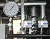
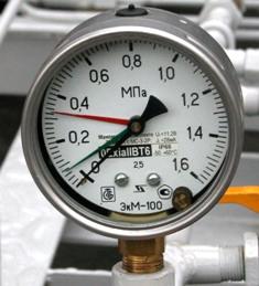
Working pressure gauges should be periodically checked at the installation site against the test gauge. The test pressure gauge is connected to the flange of the three-way valve. The plug of the three-way valve is previously placed in the zero check position, in which the device is disconnected from the measured medium and its cavity is connected to the atmosphere.
After making sure that the DUT indicator is at zero or its needle rests on the zero pin, smoothly rotate the three-way valve plug to connect the two pressure gauges (test and control) to the medium being measured. If now the readings of the two manometers coincide or differ by an amount that does not exceed the absolute error for a given measurement limit and accuracy class of the tested device, the device is suitable for further work. Otherwise, the pressure gauge under test must be dismantled and sent for repair.
Calibration of pressure gauges includes: visual inspection, checking the position of the arrow on the zero or initial mark, adjusting the arrow on the zero mark, determining the error and variation, checking the tightness of the sensitive element, determining the difference in the readings of the two arrows in two-way instruments , estimation of the adjustment force of the control arrow, calculation of the error, etc. variations in signaling device operation, chart error determination for recorders, recorder verification, device specific operation of this design. The readings of instruments calibrated in pressure units are verified by comparing these readings with the actual pressure found by the reference instrument.
The errors of liquid manometers are caused by inaccuracy in determining the height of the liquid column, in particular due to the non-vertical installation of the measuring system, drowning or floating of the float under the influence of frictional forces and the resistance of the measurement mechanism for changing the ambient temperature environment.
Calibration of measuring instruments
The inspection of volumetric measuring devices for industrial liquids includes: checking the conformity of the measuring device with the questionnaire (order form), external checking of the glucometer, checking the tightness, determining the error of the readings.
Adjustment of position regulators
It boils down to checking the wiring diagram, calibrating the tuning bodies, setting the corrected reference and the selected ambiguity zone. Special electronic control devices, electronic correcting devices, electronic differentiators, manual controllers, dynamic communication devices, etc. are manufactured to adjust the regulators.