Layout of the electrical protective device test stand
 The determination of the protective characteristics, as well as the verification of the operation of electrical devices, must be carried out on specially designed stands, which, in addition, allow monitoring of the technical condition and, if necessary, adjustment and adjustment of the tested devices.
In fig. 1 shows one variant of the main electrical circuit of the test bench. The circuit includes: circuit breaker QF1, three-phase voltage regulator PHT, power transformer TV1, rectifier VD1-VD6, ammeters AC and DC respectively A1 and A2, timer Pt, test chamber IR, relay KV1, contacts of contactors KM1: 1, KM1: 2. KM2: 1, KMZ: 1, relay contacts KV1: 1 and K.V2: 1, connectors for connecting the tested devices 1 — 6; connectors for auxiliary contacts 7 — 8.
In the diagram fig. 1 also shows the load that can be used as real circuits and equivalent circuits in which the load is simulated by electric motors, chokes and resistors.
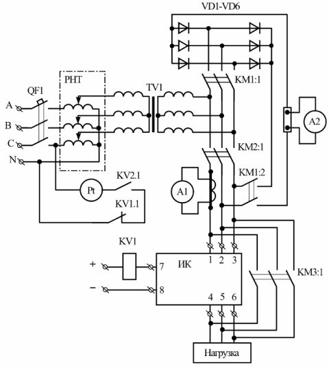
Rice. 1.Electrical schematic diagram of the electrical stand
Tests carried out in real installations can be very valuable if it is necessary to determine the behavior of a particular contactor, circuit breaker, fuse under specific operating conditions, but they can lead to damage to consumers of electricity in cases, for example, damage to the investigative apparatus.
Equivalent schemes are the most economical. In them, the load parameters can be determined with the greatest accuracy, the test conditions are easy to manufacture. The disadvantages of equivalent circuits should include, first of all, the fact that the operating conditions of electrical devices in them differ significantly from the conditions that occur in real installations.
Let's look at the operation of the test bench using the example of determining the protective characteristic of a circuit breaker.
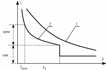
Rice. 2. Protective characteristic of the breaker: 1 — protective characteristic of the protected equipment, 2 — protective characteristic of the breaker.
In order to determine the protective characteristic of the machine under test when it is operated on alternating current, the machine QF1 is switched on and power is supplied to the coil of the contactor KM2. The current setting is carried out by the RNT regulator according to the ammeter A1 with closed contacts of the KMZ: 1. Then the automaton Q is turned off.F1 and the machine under study is installed in the test chamber.
The power supply is interrupted by the coil of the KMZ contactor. To determine the response time of the machine under study with the simultaneous closure of the switch QF1, power will be supplied to the relay coil KV2, which actuates Pt.When the switch under investigation is turned off, its block — contacts close the supply circuit of the relay KVI, which through its contact KV1: 1 will disable the electric timer.
The test bench allows you to check the maximum and thermal ratings of the machines. The tripping current is determined by gradually increasing the current in the supply circuit to the value at which the surge protector will trip.
If the breaker has an adjustable setting, the tests are carried out for all current values indicated on the scale. For each value of the setting current, 3-4 measurements should be made and the average value of the operating current should be calculated. The test result is considered satisfactory if the largest difference between the average operating current and the setting current does not exceed 10% of the setting current.
The tripping time is checked by passing a current equal in magnitude to twice the setting value at two extreme and one intermediate value of the current setting. For each value of the setpoint, also make 3 — 4 measurements and calculate the average value of the response time. The test result is considered satisfactory if the largest difference between the average response time and the corresponding average value of the time setting does not exceed ± 0.1 s for settings up to 2 s and ± 5% for settings above 2 s.
Before checking the release of the release in its original position, it is necessary to determine the reverse current.To do this, it is necessary to increase the value of the current to a value in excess of the setting so that the release begins to operate, and then decrease the current to a value where the release begins to return to its original position. Knowing the return current, you can start checking the return.
To do this, re-activate the release and after 75% of the setting time reduce the current to a value lower than the reset current and make sure that the release returns to its original position. The return check should be performed at two extremes and one intermediate value of the current setup. The result is considered satisfactory if the release has not been activated and the moving parts have returned to their original position.
Knowing the operating current and the reset current, it is possible to calculate the reset factor, i.e. the ratio of the return current to the capture current.
To check the release return time of the circuit breaker, you must apply a current to the release at which it will open, and then measure the time from the moment the current is turned off until the moment when all elements of the release return to their original position . This test is also run 3-4 times, after which the average return time is calculated. The test result is considered satisfactory if the release return time with time delay does not exceed 0.5 s, and without time delay — 0.2 s.