Power schemes for users of the second category
 In order to ensure a reliable supply of energy consumers of category II, the network scheme must have backup elements that are put into operation (after failure of the main elements) by the service personnel. In this case, there may be direct reduction of 6-20 kV lines, transformers and 0.4 kV lines, as well as mutual reduction of individual network elements (transformers through a 0.4 kV network, excess of 6-50 kV lines and transformers through a 0.4 kV).
Therefore, the basic principle of construction of a distribution network for the supply of category II receivers consists of a combination of 6-20 kV loop lines providing bidirectional supply to each transformer substation and 0.4 kV loop lines connected to one or different transformer substations. consumer power substations. It is also allowed to use automated schemes (multi-beam, two-beam) if their use increases the reduced costs of the city electricity network by no more than 5%.
Typical power supply schemes for industrial plants
The circuit shown in fig.1, provides for the possibility of two-way power supply of the transformer substation by a network with a voltage of 6-20 kV and bushings of 0.4 kV, connected to contour lines with a voltage of 0.4 kV, and is intended for powering receivers of categories II and III.
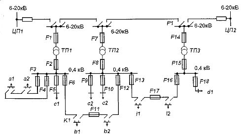
Figure 1. Power scheme for consumers of category II (6-20 kV and 0.4 kV network scheme)
The power of the transformer substations is selected with a reserve in the case of feeding consumers connected to 0.4 kV loop lines coming out of one transformer substation, i.e. the power of the transformer must be sufficient to ensure limited curtailment of the consumers' supply.
The 0.4 kV network can operate in closed mode and therefore the transformers of the transformer substation will be found to be operating in parallel across the 0.4 kV network. In this case, the power supply of the transformer substation through the 6-20 kV lines must be carried out from one source, and automatic reverse power devices are installed in the 0.4 kV transformer circuit.
In fig. 1 loop distribution lines with a voltage of 0.4 kV category II power receivers (a1, a2, b1, b2, l1, l2). Category III receivers (c1, d1) are fed from non-redundant radial lines or separate inputs to them.
For the supply of category II user, c2 has two inputs from TP2, and for users a1 and a2 - a line from one source (TP1). Such a power supply scheme is permissible if there is a centralized reserve of transformers in the city network and the possibility of replacing a damaged transformer within 24 hours.
Power supply for consumers b1, b2 and l1, l2 is carried out by loop lines with a voltage of 0.4 kV connecting TP1 and TP2, as well as TP2 and TP3.
Contour lines with a voltage of 0.4 kV contain a special distribution device, the so-called connection point (P1, P2), the design of which provides for the possibility of installing fuses on lines suitable for it.
In normal mode, the distribution network with a voltage of 0.4 kV at the connection point is open and each transformer substation supplies its own area of the network. Under these conditions, the cross-sections of wires from lines with a voltage of 6 — 20 kV and 0.4 kV and the power of the transformers are selected.
The selected parameters are further checked under the conditions resulting from normal mode violations. So, the cross-section of lines with a voltage of 6-20 kV must ensure the passage of all the power of the transformer substations connected to the loop line. In a similar way, the cross-section of 0.4 kV lines is selected, i.e. the cross-section of the wires must ensure the passage of all the power connected to the contour line with a voltage of 0.4 kV (in our example, these are the powers of consumers a1 and a2, or l1 and l2, or b1 and b2). The cross-section of the inputs to the user c2 is taken according to the power supply conditions for this user, one input at a time in case of an emergency, the second is disconnected.
The power of the transformers in the transformer substation is selected taking into account the alternative exit of neighboring transformers from operation and the surplus of power to consumers supplied only by 0.4 kV lines. So, in case of failure of transformer TP2, consumer load b2 should receive power from TP1 after installation of fuse F11, and consumer load l1 — from TP3 after installation of fuse F17.In case of transformer TP3 failure, consumer load l2 receives power from TP2, and load d1 disconnected for the period of repair or replacement of damaged transformer TP3.
Thus, the power of the transformer TP1 must be determined taking into account the need to supply the consumer b2, and the power of the transformer TPZ — taking into account the need to supply the consumer l1.
The power of the transformer TP2 must be determined taking into account the need to supply the largest of the power loads of consumers b1 and l2 (see Fig. 1). The reserve power of the transformer is determined by the configuration of the 0.4 kV voltage network, and in principle it is possible to install transformers in the transformer substation with such power, which would be sufficient to meet the needs of all users of the disconnected transformer substations. In this case, however, the cost of building the network will rise sharply.
If a fuse is installed at connection point P1, then the 0.4 kV loop line will be closed and the transformer transformers (if they meet the condition for parallel operation) will be connected to each other by parallel operation through a 0.4 kV network. In this case, the network is called semi-closed. In such a network, the level of energy losses is minimal, the quality of energy delivered to the user improves, and the reliability of the network increases.
As can be seen from fig. 1, transformers connected to only one line with a voltage of 6-20 kV are included for parallel operation.Transformers may also be connected to parallel operation, the power of which is provided by different 6-20 kV distribution lines originating from only one source, to avoid feeding a short-circuit point in a 6-20 kV network through voltage 0.4 kV from a parallel operating transformer in the circuits of transformers 0.33 kV, automatic reverse power devices must be installed.
When a network with a voltage of 0.4 kV operates in a closed mode, fuses with a rated current of two to three steps less than on the main sections of a 0.4 kV line and a transformer substation are installed at the connection points.
If the section of the 0.4 kV loop line is damaged, for example at point K1 (see Fig. 1), fuse P1 and the fuse of the head of this line in TP1 are blown. At the same time, the user continues to receive power from TP2. Locating and determining the nature of the fault, as well as the necessary switching in the network, is carried out by service personnel.
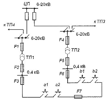
Rice. 2. Loop circuit of a network with a voltage of 6 — 20 kV and 0.4 kV
In the absence of fuse P1 in a closed network with a voltage of 0.4 kV and a failure at point K1, the fuses of the main sections of the loop line in TP1 and TP2 should blow, as a result of which the electricity supply to consumers is interrupted.
In the diagram shown in fig. 1, the loss of each element of the network is associated with a power outage of individual users. In the event of a fault, for example, in the head of a line with a voltage of 6-20 kV from CPU1, this line, together with TP1 and TP2, is switched off by relay protection on the side of CPU1.At the same time, the fuse P1 burns. As a result, the power supply to the consumers supplied by TP1 and TP2 is interrupted.
After identifying and locating the faulted area, breaker P1 turns on and the loop line receives power from CPU2, thereby restoring power to TP1 and TP2.
If the transformer is damaged in any of the transformer substations, the fuses on the 6-20 kV side and the fuses of the connecting points blow. As a result, the power supply to consumers supplied by TP is interrupted.
Note that the location of the normal opening of the 6-20 kV loop line (disconnector P1) is revealed as a result of the calculation based on the minimum power or energy losses in the network circuit. Let's note the features of the construction of closed networks with a voltage of 0.4 kV, which are widely used abroad. The presence of a closed network with a voltage of 0.4 kV ensures the parallel operation of all transformers in the network.
The distribution network of 6-20 kV should be carried out with radial lines with unidirectional power supply. Redundancy of individual network elements in case of their failure is carried out automatically through a closed network of 0.4 kV. At the same time, uninterrupted power supply to consumers is provided in case of failure of 6-20 kV lines and transformers, as well as 0.4 kV lines, depending on the method adopted for their protection (Fig. 3).
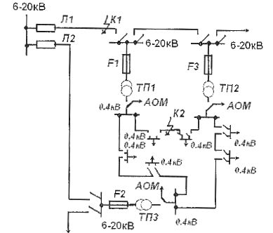
Rice. 3. Closed network with a voltage of 0.4 kV without using protection
When protecting 0.4 kV closed lines with fuses, consumers are disconnected in case of damage to the lines themselves.If the protection of the network was based on the principle of self-destruction at the point of failure due to burning of the cable and burning of its insulation on both sides, as it was in the first blindly closed networks of the USA, then the continuity of the power supply to consumers would be disturbed only in case of breakdown: at 0.4 kV inputs to them.
The indicated protection principle proved to be most acceptable for networks with single-core cables with artificial insulation laid in blocks. In networks with four-core cables with paper-oil insulation used in our country, the application of this principle creates difficulties.
Self-destruction at the point of failure is due to the fact that the arc occurring at the short-circuit point is extinguished after several periods due to the formation of a large amount of non-ionized gases released during the burning of the cable insulation and the low voltage of the network, which is not able to maintain the rainbow.
The reliable extinguishing of the arc occurs at a voltage of 0.4 kV and a current through the arc of 2.5-18 A. In the place of damage, the cable burns out, its ends are coded with a sintered mass of the cable insulation. However, as short-circuit power increased and cable burnout conditions worsened in American networks, arresters (coarse fuses) began to be used, locating the damaged section during a prolonged process of extinguishing the arc at the location of the cable fault .
Unlike the loop circuit, the selection of the parameters of individual network elements is carried out according to the power supply status of all its users in normal and after emergency modes, which occur in the network when its elements are damaged.
The cross-section of the lines with a voltage of 0.4 kV and the power of the transformers must be determined taking into account the flow distribution in a closed network and checked under the conditions of emergency mode when distribution lines are one and 6-20 kV output from working together with transformers. At the same time, the transmission capacity of the lines and the power of the transformers remaining in service must be sufficient to ensure the operation of all users of the network without limiting their power during emergency mode. The cross-section of lines with a voltage of 6-20 kV must also be determined, taking into account the decommissioning of other 6-20 kV lines.
The network with a voltage of 0.4 kV is made closed without using protection. The 6-20 kV network consists of separate distribution lines L1 and L2. On the 0.4 kV side of the transformers, automatic reverse power devices are installed, which are switched off in the event of a fault in the 6-20 kV network (lines or transformers) and feed the fault location from the undamaged line L2 through a transformer and a closed network with a voltage of 0.4 kV. The machine is switched off only when the direction of the energy flow is reversed.
In case of failure of the distribution line with a voltage of 6-20 kV at point K1, line L1 is disconnected from the processor side. The transformers connected to this line are disconnected from the 0.4 kV network by automatic reverse power devices installed in the transformer substation at a voltage of 0.4 kV. In this way, the location of the fault is localized and the supply of 0.4 kV consumers is carried out by L2 and TP3.
In the event of a fault at point K2 of the network with a voltage of 0.4 kV, the fault location must self-destruct due to cable burning, and the power supply can be interrupted only in the event of a fault at the inputs to the consumer.
Since the use of the phenomenon of spontaneous combustion of a four-core cable with viscous impregnation insulation encountered significant difficulties, automatic reverse power devices with selective fuses, which are installed on all 0.4 kV lines, began to be used to protect the network.
If the 0.4 kV line is damaged, the fuses installed at its ends blow and the power supply to consumers connected to this line is interrupted. Since the volume of consumer disconnections is small, the combination of automatic reverse power devices with fuses in the presence of a closed network with a voltage of 0.4 kV is most common in European cities.
Closed networks with a voltage of 0.4 kV are used in our country and abroad with power from a single source. This allows the use of the simplest device of an automatic device with reverse power. When a closed network is powered by different sources and a short-term decrease in the voltage on the buses of one of the processors, the direction of the power flow through the reverse power machines changes. The latter are turned off, therefore all TPs associated with this source are turned off.
In this case, the reverse supply circuit breakers must be equipped with automatic reclosing devices that operate depending on the voltage level on the secondary side of the transformers.When the voltage is restored, the switched off automatic reverse power devices are automatically turned on and the closed circuit of the network is restored. An automatic recloser greatly complicates rear power circuit breakers because an automatic air shutoff actuator and a dedicated voltage relay are required. Therefore, closed-grid circuits powered by different sources have not gained prevalence.
The closed network with a voltage of 0.4 kV provides more reliable power supply to consumers, reduced losses of electricity in the network and better voltage quality for consumers. Since such a network is supplied from a single source, it can only be used to supply category II consumers.
On the basis of a closed circuit of a network with a voltage of 0.4 kV, its modification was developed, providing for the additional installation of automatic transfer switches (ATS) in a network with a voltage of 6-20 kV, the initial element of which is automatic back-up devices. In this case, the 0.4 kV network is protected by fuses.