Adjustment and adjustment of thermal relays and circuit breaker releases
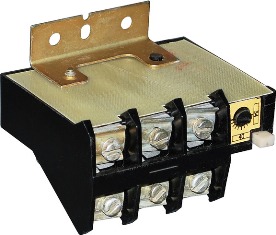
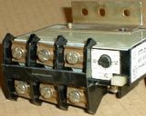 Currently, the main means of protecting electric drives from overload are thermal relaysas well as circuit breakers with thermal releases. The two-pole relays of the TRN and TRP types, as well as the three-pole relays-RTL, RTT, are the most widely distributed. The latter have improved characteristics and provide protection against unbalanced modes.
At 20% overload, the thermal relay should turn off the electric motor for no more than 20 minutes, and at double overload, in about 2 minutes. However, this requirement is often not met because the rated current of the heating element of the thermal relay does not match the rated current of the motor to be protected. The operation of thermal relays is significantly affected by the ambient temperature.
The main parameter of thermal relays is the protection characteristic during current, that is, the dependence of the response time on the magnitude of the overload.
The first of these is for a relay in a cold state (current heating begins when the relay has a temperature equal to the ambient temperature), and the second is for a relay in a hot state (overload mode occurs after the relay has been operated for 30- 40 minutes at rated current).
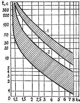
Rice. 1. Protective characteristics of the thermal relay: 1 — cold trip zone, 2 — hot trip zone
To ensure reliable and timely shutdown of the electric motor in case of overload, the thermal relay must be adjusted on a special stand. This eliminates the error due to the natural spread of the nominal currents of the factory heating elements.
When checking and adjusting the thermal protection of the stand, the so-called is used. Method of fictitious loads. A reduced voltage current is passed through the heating element, thus simulating a real load, and the response time is determined using a stopwatch. In the setting process, it is necessary to strive to ensure that 5 ... 6 times the current is turned off after 9 — 10 s and 1.5 times after 150 s (when the heater is cold).
To set up thermal relays, you can use commercially available specialized stands.
In fig. 2 shows a diagram of such a device. The device consists of a low-power load transformer TV2, to the secondary winding of which the heating element of the thermorelay KK is connected, and the voltage of the primary winding is smoothly regulated by the autotransformer TV1 (for example, LATR-2 ). The load current is controlled by an ammeter PA connected to the secondary circuit through a current transformer.
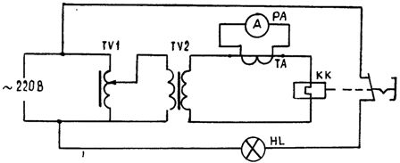
Rice. 2. Schematic diagram of the installation for checking and adjusting the thermal relays
The thermal relay is checked as follows. The knob of the autotransformer is set to the zero position and voltage is applied, then by turning the knob the load current Az = 1.5Aznominal is set and a timer controls the reaction time of the relay (at the moment when the HL lamp goes out). The operation is repeated for the remaining heating elements of the relay.
If the response time of at least one of them is not correct, the thermal relay must be adjusted. Adjustment is done with a special adjusting screw. At the same time, they achieve this at current Az = 1.5Aznominal response time is 145 — 150 s.
The regulated thermal relay must be set to the rated motor current and ambient temperature. This is done in the event that the nominal current of the heating element differs from the nominal current of the electric motor (in practice, this is generally the case) and when the ambient temperature is below the nominal (+ 40 ° C) by more than 10 ° C. The current setting of the relay can be adjusted in the range of 0.75 - 1.25 of the rated current of the heater. The setting is performed in the following sequence.
1. Determine the correction (E1) of the relay for the rated current of the motor without temperature compensation ± E1 = (Aznom- Azo) / BAZO,
where Inom — rated current of the motor, Azo is the current of the zero setting of the relay, C is the cost of dividing the eccentric (C = 0.05 for open starters and C = 0.055 for protected ones).
2. Determine the ambient temperature correction E2 = (t — 30) / 10,
where t is the ambient temperature, °C.
3. Determine the total correction ± E = (± E1) + (-E2).
With a fractional value E, it must be rounded up or down to the nearest whole, depending on the nature of the load.
4. The eccentricity of the thermal relay is transferred to the obtained correction value.
Fine-tuned thermal relays of types TRN and TRP have protection characteristics that differ slightly from the average. However, such relays do not provide protection to the electric motor in the event of a jam, as well as for electric motors that did not start in the absence of a phase.
In addition to magnetic starters ° With thermal relays in electric drives for their rare starts and protection of electric circuits from short circuits, automatic switches are used. In the presence of combined releases, such devices also protect electrical receivers from overload. Characteristic parameters of circuit breakers: minimum operating current — (1.1 … 1.6)Aznom, electromagnetic release setting — (3 — 15)Aznom, response time at the moment Az = 16Aznom — less than 1 s.
The testing of thermal elements of automatic disconnecting devices is carried out in the same way as the testing of thermal relays. The test is carried out with a current of 2Aznom at an ambient temperature of + 25 ° C. The response time of the element (35 — 100 s) must be within the limits specified in the factory documentation or established by the protective characteristics of each machine. The adjustment of the heating elements consists in installing bimetallic plates with the help of screws for the same response time at the same current.
To check the electromagnetic release of the circuit breaker, a current 15% less than the setting current (breaking current) is passed through it from the load device.The test current is then gradually increased until the apparatus shuts down. In this case, the maximum value of the operating current should not exceed the setting current of the electromagnetic release by more than 15%. The test is carried out for no more than 5 s to avoid unacceptable overheating of the switch contacts.
To check the release of low voltage, a voltage U = 0.8 Unom is applied to the breaker terminals and the device is turned on, after which the voltage is gradually reduced to the moment of operation Uc = (0.35 — 0.7) Unom.
Recently, the industry has started using semiconductor protection and control devices. Instead of conventional magnetic starters, for example, special thyristor blocks are used. Maintenance of such devices consists of periodic external inspections and performance checks.