Electrical loads
 Electric load each element of the network is called the power with which this element of the network is charged. For example, if a power of 120 kW is transmitted over a cable, then the load on the cable is also 120 kW. In the same way, we can talk about the load on the bus of the substation or the transformer, etc. The magnitude and nature of the electrical load depends on the consumer of electrical energy, which can be called the receiver of electrical energy.
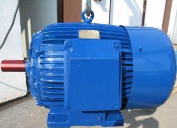
The most common and important receiver in production is the electric motor. The main consumers of electrical energy in industrial enterprises are three-phase AC motors. The electrical load on an electric motor is determined by the magnitude and nature of the mechanical load.
Loads must be covered by a source of electrical energy, which is a power plant. Typically, a number of electrical network elements exist between the generator and the consumer of electrical energy.For example, if the motors driving the mechanisms in the workshop are powered by a 380 V network, then a workshop transformer substation should be located in the workshop or near the workshop, on which power transformers are installed to supply the workshop installations (to cover the workshop is loading).
Transformers via cables or overhead wires are fed either from a more powerful substation, or from an intermediate high-voltage distribution point, or, which is often found in enterprises, from an enterprise thermal power plant. In all cases, load coverage is carried out by the generators of the power plant. In this case, the load has a minimum value at the end point, for example in a store.
As you get closer to the power source, the load increases due to energy losses in the transmission links (in wires, transformers, etc.). The highest value is reached at the source of energy — at the generator of the power plant.
Since the load is measured in units of power, it can be active Pkw, reactive QkBap and complete C = √(P2 + Q2) kVA.
The load can also be expressed in units of current. If, for example, a current Az = 80 A flows through the line, then this 80 A is the load on the line. When the current passes through any element of the installation, heat is generated, as a result of which this element (transformer, converter, buses, cables, wires, etc.) is heated.
The permissible power (load) on these elements of the electrical installation (machines, transformers, devices, wires, etc.) is determined by the value of the permissible temperature.The current flowing through the wires, in addition to power losses, causes voltage losses that should not exceed the values specified in the guidelines.
In real installations, the load in the form of current or power does not remain unchanged during the day, and therefore certain terms and concepts for different types of loads are introduced in the practice of calculations.

Rated active power of the electric motor — the power developed by the shaft motor at the rated armature (rotor) voltage and current.
Rated power of each receiver, except for the electric motor, it is the active power P consumed by a nongon (kW) or apparent power Сn (kVA) at rated voltage.
Passport power Rpasp of the electrical receiver in intermittent mode reduced to rated continuous power at duty cycle = 100% according to the formula Pn = Ppassport√PV
In this case, PV is expressed in relative units. For example, a motor with a nominal power Ppassport = 10 kW at a duty cycle = 25%, reduced to a nominal continuous power = 100%, will have a power Pn = 10√25 = 5 kW.
Group rated power (installed power) — the sum of the rated (passport) active powers of individual working electric motors, reduced to PV = 100%. For example, if Pn1 = 2.8, Pn2 = 7, Ph3 = 20 kW, R4 passes = 10 kW at duty cycle = 25%, then Pn = 2.8 + 7 + 20 + 5 = 34.8 kW.
Calculated, or maximum active, Pm, reactive Qm and total Cm power, as well as maximum current Azm represent the largest of the average values of powers and currents for a certain period of time, measured 30 minutes. As a result, the estimated peak power is otherwise called the half-hour or 30-minute peak power Pm = P30.Accordingly, Azm =Azzo.
Approximate maximum current Azm = I30 = √ (stm2 + Vm2)/(√3Unot Azm = I30 =Pm/(√3UnСosφ)where V.osφ — the weighted average value of the power factor for the expected time (30 minutes)
See also: Coefficients for calculating electrical loads
Determination of design loads for industrial enterprises and rural areas

A graphic of the electrical load is usually called a graphical representation of the consumed power over a certain period of time. Distinguish between daily and annual load schedules. The daily graph shows the dependence of the consumed power on the weather during the day. The load (power) is arranged vertically and the hours of the day are displayed horizontally. The annual schedule determines the dependence of the consumed power on the time of the year.
In their form, the graphs of electrical loads for different industries and consumers are very different from each other.
It is necessary to distinguish between schedules: shop load and bus load at the main switchgear of your own power plant or substation. These two graphs differ from each other primarily in the absolute values of the hourly loads, as well as in their appearance.
The schedule for the tires of the power plant (GRU) is obtained by summing the loads for all stores of the enterprise and other consumers, including external consumers. At the same time, the power losses in the shop transformers and the wires leading to the transformers must be added to the shop loads.It is quite natural that the power of GRU buses significantly exceeds the power of each individual substation.
Read more about it here: Electrical load curves
For the electrical loads of residential buildings: Daily load curves of residential buildings