Checking electrical circuits when setting up and repairing electrical equipment
 During the adjustment or repair of electrical equipment, electrical circuits can be checked directly or by grounding.
The direct test method is used when the beginning and end of the electrical circuit under test are located in close proximity to each other and no auxiliary circuits are required.
The grounding method is intended for testing those electrical circuits in which the beginnings and ends are located at a considerable distance. Its use is accompanied by the use of auxiliary circuits, which are grounding wires, screens and metal sheaths of cables and cores, specially laid wires, etc.
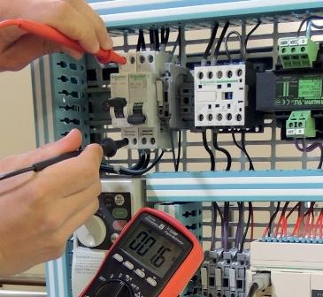
For each method of checking the electrical circuit, devices are used, the principle of operation of which is similar to the principle of operation of the probe (Fig. 1, a).
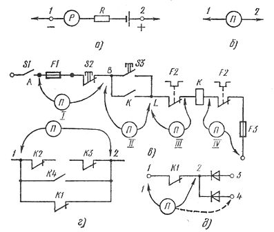
Rice. 1. Schematic (a) and probe symbol (b), circuit test example (c) and typical errors during testing (d, e)
When the probe circuit is closed across the circuit under test, the needle of the device P is deflected in the same way as when terminals 1 and 2 are short-circuited. Resistor R serves to limit the current flowing through the meter. In the following figures, instead of the complete circuit of the probe, its symbol shown in fig. 1, b.
Let's consider, using an example of a fragment of an electric drive control circuit (Fig. 1, c), the procedure for checking electric circuits. In any case, it is advisable to start the inspection process from the supply circuits, for example from point A.
Probe P is connected to points A and B, which allows you to check the circuit between them, and when you press the button S2 — the serviceability of the button and the correctness of the circuit between points A and B, and thus confirm that the circuit between them is formed through the S2 button contact and not through any other circuit element. Then the probe is connected to points B and L (pos. II in Fig. 1, c), combining the circuit check with the S3 button serviceability check. The sequence of subsequent checks is shown in fig. 1, in the respective positions of the probe.
When testing an electric circuit with a probe, it is necessary to visually check the number of cores of the cables and wires connected to the mounting points of the circuit. For example, at the mounting point B, two wires must be connected to the terminal of the closing button S3. - a jumper from the button S2 and a wire to the contactor contact K.
When checking circuits, special attention should be paid to observing polarity in DC circuits and phasing in AC circuits.
Let's look at some of the most common mistakes made when checking electrical circuits. For example, the circuit 1 — 2 (Fig. 1, d) is manipulated by the contact of the relay K1, therefore, when the probe is connected to points 1 and 2, there is no open circuit in the contact circuit K2, short circuit or closing of contact K4. Therefore, to test the circuits connected to points 1 and 2, you must first open the relay contact K1.
Another type of error resulting from the formation of spurious circuits through the forward p-n junction resistance of a semiconductor diode, illustrated in Fig. 1, d. When connecting the negative probe of the P probe to point 1, the device will give the same readings as when connecting another probe to point 2, as well as to points 3, 4. This will not happen if you reverse the polarity of the connection on the probe.
The examined examples showed the implementation of this technological transition in a direct way.
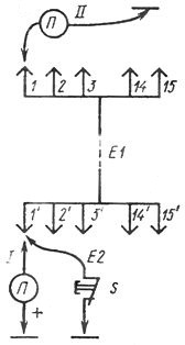
Rice. 2… Check electrical circuits by grounding
The grounding test begins with the installation of a temporary jumper E2 with a button installed in it at one end of the tested cable E1... Then, touching the probe of the probe P to the core, check the integrity of the auxiliary circuit: common wire (in this case «grounding ») — button 5 — wire G — probe P — probe «plus» of probe P — common wire.
If the probe shows a closed circuit, press and release button 5. If the jumper is installed correctly, the P probe should change its reading.
After checking the installation of jumper E2, they begin to look for a ground wire at the second end of the cable by connecting the P probe in series with the wires and watching its readings.If the probe shows a closed circuit, consider the desired core found, and after switching the ground jumper E2 to another core, continue to look for it at the other end of the cable.
The reason for the most frequent errors in testing by the grounding method is the assignment of the same number to different electrical circuits and the formation of a false circuit when connecting the tested cores of a wire or cable to a ground wire.
To prevent such errors, after finding the next circuit, disconnect and reconnect the ground wire with the S button. If the probe responds to the disconnection of the ground wire, the circuit has been found correctly. Otherwise, it is necessary to find and eliminate the cause of the short circuit of the tested circuit with the ground wire.