Indicators of the quality of electricity in electrical networks
 In accordance with GOST 13109-87, basic and additional power quality indicators are distinguished.
Among the main indicators of the quality of electricity, the determination of the properties of electric energy characterizing its quality includes:
1) voltage deviation (δU, %);
2) the voltage change range (δUT,%);
3) the dose of voltage fluctuations (ψ, %);
4) the coefficient of non-sinusoidality of the voltage curve (kNSU, %);
5) coefficient of the nth component of the harmonic voltage of odd (even) order (kU (n), %);
6) the coefficient of the negative sequence of voltages (k2U, %);
7) zero sequence voltage ratio (k0U, %);
8) the duration of the voltage drop (ΔTpr, s);
9) impulse voltage (Uimp, V, kV);
10) frequency deviation (Δe, Hz).
Additional power quality indicators, which are forms of recording the main power quality indicators and are used in other regulatory and technical documents:
1) the coefficient of amplitude modulation of voltages (kMod);
2) the coefficient of unbalance between phase voltages (kneb.m);
3) unbalance factor of phase voltages (kneb.f).
Let's note the permissible values of the specified indicators for the quality of electricity, expressions for their definition and scope. During 95% of the time of the day (22.8 hours), the power quality indicators should not exceed the normal permissible values, and at all times, including emergency modes, they should be within the maximum permissible values.
The control of the quality of electricity at characteristic points of the electrical networks is carried out by the personnel of the electrical network enterprise. In this case, the duration of the measurement of the power quality indicator should be at least one day.
Voltage deviations
Voltage deviation is one of the most important indicators of power quality. The voltage deviation is found by the formula
δUt = ((U (t) — Un) / Un) x 100%
where U (t) — the effective value of the voltage of the positive sequence of the fundamental frequency or simply the effective value of the voltage (with a non-sinusoidal factor less than or equal to 5%), at the moment T, kV; Non-nominal voltage, kV.
The quantity Ut = 1/3 (UAB (1) + UPBC (1) + UAC (1)), where UAB (1),UPBC (1), UAC (1)-RMS values of phase-to-phase voltage at the fundamental frequency.
Due to changes in loads over time, changes in the voltage level and other factors, the magnitude of the voltage drop in the network elements changes and, accordingly, the voltage level UT.As a result, it turns out that at different points of the network at the same moment in time and at one moment in different time, the voltage deviations are different.
The normal operation of electrical receivers with a voltage of up to 1 kV is ensured provided that the voltage deviations at their input are equal to ± 5% (normal value) and ± 10% (maximum value). In networks with a voltage of 6 — 20 kV, a maximum voltage deviation of ± 10% is set.
The power consumed by incandescent lamps is directly proportional to the supplied voltage to the power of 1.58, the luminous power of the lamps is to the power of 2.0, the luminous flux is to the power of 3.61, and the life of the lamp is to the power of 13.57. The operation of fluorescent lamps depends less on voltage deviation. Thus, their service life changes by 4% with a voltage deviation of 1%.
The reduction of lighting in workplaces occurs with a decrease in tension, which leads to a decrease in the productivity of workers and deterioration of their vision. With large voltage drops, fluorescent lamps do not light or blink, which leads to a decrease in their service life. As the voltage increases, the service life of incandescent lamps is reduced dramatically.
The speed of rotation of asynchronous electric motors and, accordingly, their operation, as well as the reactive power consumed, depend on the voltage level. The latter is reflected in the amount of voltage and power losses in network sections.
The decrease in voltage leads to an increase in the duration of the technological process in electrothermal and electrolysis plants, as well as to the impossibility of stable reception of television broadcasts in utility networks. In the second case, so-called voltage stabilizers are used, which themselves consume significant reactive power and which have power losses in the steel. Scarce transformer steel is used for their production.
In order to ensure the necessary voltage of the low-voltage buses of all TPs, the so-called countercurrent regulation in the food center. Here, in the maximum load mode, the maximum allowable voltage of the processor buses is maintained, and in the minimum load mode, the minimum voltage is maintained.
In this case, the so-called local regulation of the voltage of each transformer station by placing the switch of the distribution transformers in the appropriate position. In combination with centralized (in the processor) and defined local voltage regulation, regulated and unregulated capacitor banks, also called local voltage regulators, are used.
Reducing tension
Voltage swing is the difference between the peak or rms voltage values before and after a voltage change and is determined by the formula
δUt = ((Ui — Уi + 1) / √2Un) x 100%
where Ui and Ui + 1- the values of the following extremes or extrema and the horizontal part of the envelope of the amplitude voltage values.
Voltage swing ranges include single voltage changes of any form with a repetition rate of twice per minute (1/30 Hz) to once per hour, with an average rate of voltage change of more than 0.1% per second (for incandescent lamps) and 0.2% per second for other receivers.
Rapid changes in voltage are caused by the shock mode of operation of the motors of metallurgical roller mills of traction installations of railways, meadow furnaces for the production of steel, welding equipment, as well as frequent starts of powerful asynchronous electric motors with squirrels, when they start the reactive power is a few percent of the short-circuit power.
The number of voltage changes per unit time, i.e. the frequency of voltage changes is found by the formula F = m / T, where m is the number of voltage changes during time T, T is the total time of observing the voltage swing.
The main requirements for voltage fluctuations are due to human eye protection considerations. It was found that the highest sensitivity of the eye to light flicker is in the frequency range equal to 8.7 Hz. Therefore, for incandescent lamps that provide working lighting with significant visual voltages, the voltage change is allowed no more than 0.3%, for pumping lamps in everyday life — 0.4%, for fluorescent lamps and other electrical receivers — 0.6.
The permissible swing ranges are shown in fig. 1.
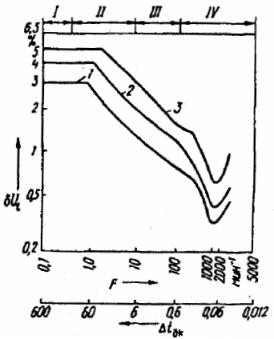
Rice. 1. Permissible ranges of voltage fluctuations: 1 — work lighting with incandescent lamps at high visual voltage, 2 — domestic incandescent lamps, 3 — fluorescent lamps
Region I corresponds to the operation of pumps and household appliances, II — cranes, hoists, III — arc furnaces, manual resistance welding, IV — operation of reciprocating compressors and automatic resistance welding.
To reduce the range of voltage changes in the lighting network, separate power supply of the receivers of the lighting network and the power load from different power transformers, longitudinal capacitive compensation of the power network, as well as synchronous electric motors and artificial sources of reactive power (reactors or capacitor banks whose current is generated using controlled valves to obtain the required reactive power).
Dose of voltage fluctuations
The dose of voltage fluctuations is identical to the range of voltage changes and is introduced into existing electrical networks as soon as they are equipped with appropriate devices. When using the indicator "dose of voltage fluctuations", an assessment of the admissibility of the range of voltage changes may not be made, since the considered indicators are interchangeable.
The dose of voltage fluctuations is also an integral characteristic of voltage fluctuations that cause irritation to a person accumulated over a certain period of time due to flashing light in the frequency range of 0.5 to 0.25 Hz.
The maximum permissible value of the dose from voltage fluctuations (ψ, (%)2) in the electrical network to which the lighting installations are connected should not exceed: 0.018 — with incandescent lamps in rooms where significant visual voltage is required; 0.034 — with incandescent lamps in all other rooms; 0.079 — with fluorescent lamps.
Non-sinusoidal factor of the voltage curve
When working in a network of powerful rectifier and converter installations, as well as arc furnaces and welding installations, i.e. non-linear elements, the current and voltage curves are distorted. Non-sinusoidal current and voltage curves are harmonic oscillations of different frequencies (industrial frequency is the lowest harmonic, all others relative to it are higher harmonics).
Higher harmonics in the power supply system cause additional energy losses, reduce the service life of cosine capacitor batteries, electric motors and transformers, lead to difficulties in setting up relay protection and signaling, as well as the operation of electric drives controlled by thyristors, etc. .
The content of higher harmonics in the electrical network is characterized by the non-sinusoidal coefficient of the voltage curve kNSU which is determined by the expression
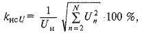
where N is the order of the last of the considered harmonic components, Uн — effective value of the nth (н = 2, ... Н) component of the harmonic voltage, kV.
Normal and maximum permissible values kNSU should not exceed, respectively: in an electrical network with voltage up to 1 kV — 5 and 10%, in an electrical network 6 — 20 kV — 4 and 8%, in an electrical network 35 kV — 3 and 6%, in the electrical network 110 kV and above 2 and 4%.
To reduce higher harmonics, power filters are used, which are a series connection of inductive and capacitive resistance tuned to resonance at a certain harmonic. To eliminate harmonics at low frequencies, converter installations with a large number of phases are used.
Coefficient nth component of harmonic voltage of odd (even) order
Coefficient nThis harmonic component of the voltage of the odd (even) order is the ratio of the effective value of the nth harmonic component of the voltage to the effective value of the voltage of the fundamental frequency, i.e. kU (n) = (Un/Un) x 100%
By the value of the coefficient kU (n), the spectrum is determined by n-x harmonic components, for the suppression of which the corresponding power filters must be designed.
Normal and maximum permissible values should not exceed, respectively: in an electrical network with a voltage up to 1 kV — 3 and 6%, in an electrical network 6 — 20 kV 2.5 and 5%, in an electrical network 35 kV — 2 and 4%, in an electrical network 110 kV and above 1 and 2%.
Voltage imbalance
The voltage imbalance occurs due to the loading of single-phase electrical receivers. Since distribution networks with voltages above 1 kV operate with an isolated or compensated neutral, then voltage asymmetry due to the appearance of negative sequence voltage. Asymmetry manifests itself in the form of inequality line and phase voltage and a negative consecutive factor is characterized:
k2U = (U2(1)/ Un) x 100%,
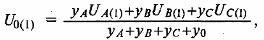
where U2(1) is the rms value of the negative sequence voltage at the fundamental frequency of the three-phase voltage system, kV. U value2(1) can be obtained by measuring three voltages at the fundamental frequency, i.e. UA(1), UB (1), UB (1)... Then
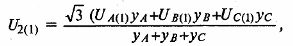
where yA, yB and y° C — phase conductivity A, B and ° C receiver.
In networks with voltages above 1 kV, voltage asymmetry occurs mainly due to single-phase electrothermal installations (indirect arc furnaces, resistance furnaces, furnaces with induction channels, electroslag melting installations, etc.).
Does the presence of a negative sequence voltage lead to additional heating of the excitation windings of synchronous generators and an increase in their vibrations, additional heating of electric motors and a sharp decrease in the service life of their insulation, a decrease in the reactive power generated by power capacitors, additional heating of lines and transformers? increasing the number of false alarms of the relay protection, etc.
On the terminals of a symmetrical electrical receiver, the normally permissible unbalance ratio is 2%, and the maximum permissible is 4%.
The influence of unbalance is greatly reduced when single-phase power consumers are supplied by separate transformers, as well as when controlled and uncontrolled balancing devices are used, which compensate for the negative sequence equivalent current consumed by single-phase loads.
In four-wire networks with a voltage of up to 1 kV, an imbalance caused by single-phase receivers associated with the phase voltages is accompanied by the passage of current in the neutral wire and, therefore, the appearance of a zero-sequence voltage.
Zero sequence voltage factor k0U = (U0(1)/ Un.f.) x 100%,
where U0 (1) — effective zero-sequence voltage value of the fundamental frequency, kV; Un.f. — nominal value of the phase voltage, kV.
The quantity U0(1) is determined by measuring the three phase voltages at the fundamental frequency, i.e.
where tiA, vB, c° C, yO — conductivity of phases A, B, C of the receiver and conductivity of the neutral conductor; UA(1), UB (1), UVB (1) - RMS values of the phase voltages.
Allowable value U0(1) limited by voltage tolerance requirements which are satisfied by zero sequence factor of 2% as normal level and 4% of maximum level.
The reduction of the value can be achieved by rational distribution of a single-phase load between the phases, as well as by increasing the cross-section of the neutral wire to the cross-section of the phase wires and using transformers in a distribution network with a star-zigzag connection group.
Voltage sag and intensity of voltage sags
Voltage dip — this is a sudden significant reduction in voltage at a point of the electrical network, followed by a recovery of the voltage to the initial level or close to it after a time interval from several periods to several tens of seconds.
Duration of voltage drop ΔTpr is the time interval between the initial moment of voltage drop and the moment of recovery of the voltage to the initial level or close to it (Fig. 2), i.e. ΔTpr = Tvos — Trano
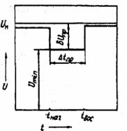
Rice. 2. Duration and depth of voltage drop
Meaning ΔTpr varies from several periods to several tens of seconds. The voltage drop is characterized by the intensity and depth of the dip δUpr, which is the difference between the nominal value of the voltage and the minimum effective value of the voltage Umin during the voltage drop and is expressed as a percentage of the nominal value of the voltage or in absolute units.
The quantity δUpr is determined as follows:
δUpr = ((Un — Umin)/ Un) x 100% or δUpr = Un — Umin
Voltage sag intensity m* represents the frequency of occurrence in the network of voltage sags of a certain depth and duration, i.e. m* = (m (δUpr, ΔTNC)/М) NS 100%, where m (δUpr, ΔTNS) — number of voltage drops depth δUpr and duration ΔTNS during T; M — the total number of voltage drops during T.
Some types of electrical devices (computers, power electronics), therefore, power supply projects for such receivers must provide for measures to reduce the duration, intensity and depth of voltage dips. GOST does not indicate the permissible values for the duration of voltage drops.
Impulse voltage
A voltage surge is a sudden change in voltage followed by a recovery of the voltage to its normal level over a time period of a few microseconds to 10 milliseconds. It represents the maximum instantaneous value of the impulse voltage Uimp (Fig. 3).
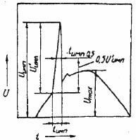
Rice. 3. Impulse voltage
The impulse voltage is characterized by the impulse amplitude U 'imp, which is the difference between the voltage impulse and the instantaneous value of the voltage of the fundamental frequency corresponding to the moment of the beginning of the impulse. Pulse duration Timp — the time interval between the initial moment of the voltage pulse and the moment of recovery of the instantaneous value of the voltage to the normal level. The width of the pulse can be calculated Timp0.5 at the level of 0.5 of its amplitude (see Fig. 3).
The impulse voltage is determined in relative units by the formula ΔUimp = Uimp / (√2Un)
Sensitive to voltage pulses are also such electrical receivers as computers, power electronics, etc. Impulse voltages appear as a result of switching in the electrical network. Impulse voltage reduction measures should be considered when designing specific power supply designs. GOST does not specify the permissible values of the impulse voltage.
Frequency deviation
Changes in frequency are due to changes in the overall load and characteristics of the turbine speed controllers. Large frequency deviations result from slow, regular load changes with insufficient active power reserve.
Voltage frequency, unlike other phenomena that degrade the quality of electricity, is a system-wide parameter: all generators connected to one system generate electricity at a voltage with the same frequency — 50 Hz.
According to Kirchhoff's first law, there is always a strict balance between the production of electricity and the production of electricity. Therefore, any change in the power of the load causes a change in the frequency, which leads to a change in the generation of active power of the generators, for which the «turbine-generator» blocks are equipped with devices that allow adjusting the flow of energy carrier in the turbine depending from frequency changes in the electrical system.
With a certain increase in the load, it turns out that the power of the "turbine-generator" blocks is exhausted. If the load continues to increase, the balance settles at a lower frequency—frequency drift occurs. In this case, we are talking about a deficit of active power to maintain the nominal frequency.
Frequency deviation Δf from the nominal value en is determined by the formula Δf = f — fn, where is — the current value of the frequency in the system.
Changes in frequency above 0.2 Hz have a significant impact on the technical and economic characteristics of electrical receivers, therefore the normal allowable value of frequency deviation is ± 0.2 Hz, and the maximum allowable value of frequency deviation is ± 0.4 Hz . In emergency modes, a frequency deviation of +0.5 Hz to — 1 Hz is allowed for no more than 90 hours per year.
Deviation of the frequency from the nominal leads to an increase in energy losses in the network, as well as to a decrease in the productivity of technological equipment.
Voltage amplitude modulation factor and unbalance factor between phase and phase voltages
Amplitude modulating voltage characterizes voltage fluctuations and is equal to the ratio of the half-difference of the largest and smallest amplitude of the modulated voltage, taken for a certain time interval, to the nominal or base value of the voltage, i.e.
kmod = (Unb — Unm) / (2√2Un),
where Unb and Unm — the largest and smallest amplitude of the modulated voltage, respectively.
Unbalance factor between phase voltagesne.mf characterizes the phase-phase voltage imbalance and is equal to the ratio of the swing of the phase-phase voltage imbalance to the nominal value of the voltage:
kne.mf = ((Unb — Unm) /Un) x 100%
where Unb and Unm-the highest and lowest effective value of the three phase phase voltages.
Phase voltage imbalance factor kneb.f characterizes the phase voltage imbalance and is equal to the ratio of the swing of the phase voltage imbalance to the nominal value of the phase voltage:
kneb.ph = ((Unb.f — Unm.f) /Un.f) x 100%,
where Unb and Unm — the highest and lowest effective value of the three phase voltages, Un.f — nominal value of the phase voltage.
Read also: Measures and technical means to improve the quality of electrical energy