Types and designs of indirect electric resistance furnaces
 Methods of loading and unloading heated products, as well as methods of moving them electric resistance furnaces largely determine both their design and operational properties. In fig. 1 shows the main types of electric resistance furnaces, both intermittent action (cell) and continuous action (methodical), illustrating the development of ways of their mechanization.
Number I indicates the types of batch furnaces in which the product is stationary during the heating process and only loading and unloading are mechanized.
Index 1 refers to a chamber oven with a side door through which usually small items are manually loaded into the chamber. This is a universal oven without mechanization.
Index 2 — a shaft furnace with an opening lid. Here, the loading and unloading of the products is done through the top opening of the furnace and therefore they can be mechanized using a workshop crane or hoist located above the furnace.Lifting and retracting the cover to the side can be done manually (with a lever) or with the help of a crane or hoist or finally with the help of a special hydraulic or electromechanical mechanism.
Index 3 corresponds to a bell furnace. Its kit includes several lined stands, on which a bell (bell) with heaters can be installed with the help of a crane. Loading and unloading is carried out using a bridge crane with the cap removed (installed on another stand). Moving the hood from one stand to another is also done using the edge of the bridge.
Index 4 — bogie chamber furnace. These ovens are designed to heat large items that cannot be loaded manually. The furnace chamber itself stands on columns (or foundations), and its bottom is a lined trolley, which, with the help of a winch or a drive located on it (self-propelled), can move on rails from under the furnace. Loading and unloading of the cart is done with an overhead crane.
Index 5 marks the elevator oven. The furnace chamber stands on tall columns, its bottom can be raised into the furnace or lowered with a load using a hydraulic lift. In the lower position, the bottom of the furnace becomes its rollers on rails and can be loaded and unloaded from under the furnace in the workshop under the overhead crane. Furnace designs 2, 3 and 5 can be sealed and operated in a special atmosphere or vacuum.
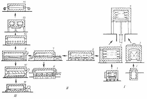
Rice. 1. The main types of saddle and batch furnaces
In numbers II and III Continuous furnaces are indicated, in which the heated products move from one end of the furnace to the other, and their number II furnaces are indicated, in which the movement of products is carried out periodically, in kicks, and figure III indicates the furnaces, in which this movement takes place continuously.
Index 6 — tunnel furnace, in which the products are placed on stacked carts, pass through a tunnel-shaped furnace chamber. After a certain period of time, all the carts move to a length equal to the length of one carriage, one of them leaving the unloading oven, while from the opposite end of the oven another loaded cart enters its chamber.
Index 7 shows an extrusion oven. A heat-resistant pallet of products is mounted on the loading table (right). The doors at the ends of the oven are opened periodically and the pusher (hydraulic or electromechanical) pushes the pallet into the oven, forcing the entire row of pallets located in the oven on refractory rails of the hearth to move. In this case, the leftmost tray comes out of the oven, after which the doors close.
Index 8 marks a furnace for pedestrian hearths. At the bottom of the furnace, according to its length, heat-resistant beams are installed, which, by means of a drive, receive a reciprocating-forward movement. In this case, the beams before moving from the loading end of the furnace are lifted from the grooves on the bottom, the lower part of the oven and move them along the oven. Before the reverse movement of the beam is lowered into the grooves of the bottom, the products sit on the bottom and do not participate in the return movement of the beams. In this way, the products periodically, in steps, move through the furnace from the loading end to the unloading end.
Index 9 for conveyor oven.In the furnace chamber, a chain conveyor is stretched over two shafts, the mesh of which consists of woven mesh or stamped or cast chain links. As the drive shaft (on the discharge side) rotates, the conveyor moves smoothly, carrying with it the products loaded onto it at the loading (right) end of the kiln. The construction of the conveyor can be very different.
Index 10 refers to a rotary kiln. The screw is located in the furnace chamber - a heat-resistant drum with an Archimedean spiral. As the drum rotates, the products roll into the drum, moving gradually from its loading end to its discharging end.
Index 11 shows a pulsating furnace with a furnace. At the bottom of the chamber, the oven is on rollers heat-resistant hearth in the form of a trough, on which the heating end of the furnace (on the right) is arranged with heated parts. With the help of an eccentric drive, the pod receives a reciprocating movement, and its backward movement (towards loading) is smooth, and towards unloading it is sharp, under the action of a spring with a shock on the shock absorbers. Because of this, the products during the backward movement follow the same path as below, while during the forward movement they, by momentum of impact, slide forward relative to the hearth. As a result, the products are gradually moved by pulses from the charging end of the furnace to the discharge.
Index 12 indicates a furnace with roller tables. Heat-resistant rollers are mounted in the bottom of the chamber, they slowly rotate counterclockwise. Because of this, the product placed on the rollers on the right (unlike the previous three types of furnaces, this furnace is designed for heating large products) is gradually transported along the furnace to its discharge end.
Index 13 refers to a rotary kiln. It is essentially a conveyor oven wound on a ring. The ring-shaped rotating hearth causes the product placed on it through the loading door (in the side wall not shown in the figure) to complete a full circle in the furnace to the unloading door located next to the loading door.
Index 14 for a drawing furnace used for heating wires or strips. At the ends of the furnace are drums with wire or tape stretched between them. As the spools rotate from one of them the tape (or wire) winds and wraps around the other.
Low temperature furnace designs
Low temperature furnaces cannot be highly efficient because natural convection heat transfer coefficients are low. The process can be enhanced by introducing artificial circulation by installing a suction fan on the roof of the furnace or cabinet, and in order to reduce the heat consumption for heating the air, it can be organized circularly. In this case, the fan, sucking the air in the upper part of the furnace, drives it along the side heat-insulated channel and blows it out in the lower part of the furnace.
If it is necessary to dry the products and therefore remove the evaporated moisture from the heated parts, then a mixed circulation is organized, in which part of the air is sucked in by the fan from the cabinet, and part from the room (Fig. 2). The maximum heating temperature of the products in this type of ovens and dryers usually does not exceed 200 — 300 ° C.
Rice. 2. Natural circulation oven: 1 — heating elements, 2 — outer frame, 3 — inner frame, 4 — thermal insulation, 5 — parts shelf, 6 — damper for air regulation.
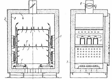
The design of a closed-loop furnace for heating small metal products in a layer or long products is shown in Fig. 3.
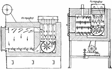
Rice. 3. Chamber furnaces with forced circulation of the atmosphere and an electric heater
It is a shaft furnace for tempering steel products, into which baskets of heat-resistant material with a grid or perforated bottom are inserted and filled with the products to be heated.
The heaters are located on the side of the oven, around the basket, but are separated from it by a heat-resistant screen to prevent direct radiation and the associated overheating of the products adjacent to the basket walls. At the bottom, the oven is equipped with a fan that drives the heated air through the baskets. This air is then deflected radially into the annular space between the basket and the oven walls and is heated, washing the heaters.
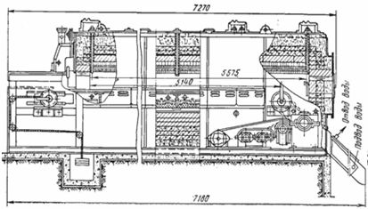
In fig. 4 shows an oven for drying welding electrodes at a temperature of 400 ° C. Furnace power 210 kW, electrodes are placed on carts, frames and with the help of a hydraulic pusher and puller are conducted through the oven. The furnace has an internal fan 6 as well as external fans 10.
The heaters are located on the side walls of the furnace. Thus, in this oven, the air flows are directed perpendicular to the line of movement of the products. Such furnaces can be built multi-zone.
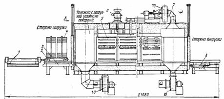
Rice. 4. Electric pusher drying oven: 1 — pusher, 2 — cart, 3 — table, 4 — frames for placing electrodes, 5 — heating chamber, 6 — furnace fan, 7 — air duct, 8 — dredger, 9 — hydraulic door lift drive, 10 — external fan
Medium temperature furnace designs
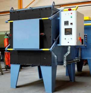
Medium temperature furnaces for heat treatment are extremely diverse. The simplest and at the same time universal furnace is the chamber furnace (Fig. 5). It consists of a rectangular chamber with fire-resistant lining and thermal insulation, covered with a roof and placed in a metal casing.
The furnace is loaded and unloaded through the opening in the front wall, covered with a door. The heaters are located in the hearth and on the side walls of the furnace, less often on the roof. In very large ovens, the heaters are located both on the back of the oven and on the doors to ensure a more even temperature distribution in the oven chamber. Bottom heaters are usually covered with refractory plates on which the heated products are placed.
The doors of chamber furnaces, as a rule, are made of lifting, in small ovens with manual or foot drive (with foot drive the worker's hand remains free), in larger ones - with electromechanical ones. In the second case, limit switches are installed in the upper and lower positions of the door, which turn off the electric motor in the end positions.
Rice. 5. Chamber electric furnace with metal heaters and a flame curtain: 1 — door, 2 — lifting mechanism of the door, 3 — outlet of the heater, 4 — casing, 5 — lining, 6 — side heaters, 7 — roof heaters, 8 — hearths, 9 — heaters, 10 — flame curtain device.
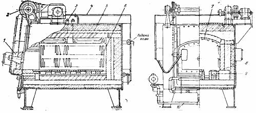
Chamber furnaces on trolleys are used for annealing or other heat treatment of large parts that cannot be loaded into the furnace manually. They are a chamber without a bottom and usually without a front wall standing on columns (Fig.6) and a trolley on rollers, on which the hearth and the front wall of the furnace are mounted, moving on rails with the help of an electric drive or an electromechanical winch. The trolley starts from under the oven, the parts are loaded onto it with a crane, then it moves under the chamber and the oven is switched on for heating.
Rice. 6. Chamber furnace with a bogie hearth: 1 — heaters, 2 — refractory masonry, 3 — thermal insulation, 4 — thermocouple, 5 — drawer, 6 — door, 7 — cage
After the end of the annealing cycle, the carriage again leaves the furnace and is unloaded. Furnace heaters are usually located on the sides, back and front walls and in the hearth, and sometimes also to provide more even heating along the vault. The bottom and front wall heaters are powered by flexible cables or blade contacts. Such furnaces are economical only with a large charge, reaching a capacity of 100 tons and more and a capacity of 3000 — 5000 kW.
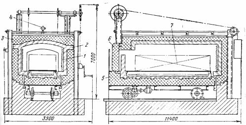
The second general group of batch furnaces are shaft furnaces. They are made in the form of round, square or rectangular shafts, open at the top and covered with a lid (Fig. 7).
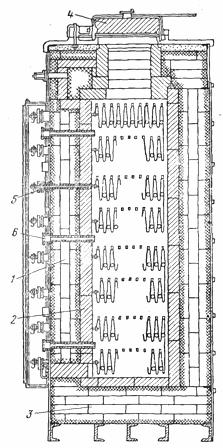
Rice. 7. Shaft electric furnace: 1 — heaters, 2 — refractory masonry, 3 — thermal insulation, 4 — furnace cover, 5 — heater outlet, 6 — thermocouple.
Heaters in shaft furnaces are usually installed on the side walls (bottom heaters are rarely installed, more so in flat rectangular furnaces). Sometimes in round furnaces designed for heating a hollow cylindrical charge (wire bundles, rolls of tin), in addition, a vertical central heater is located along the axis. Special heat-resistant guides protect the heaters from damage when items are placed in or removed from the oven or baskets of items.
Shaft furnaces are sometimes made very deep for heat treatment of shafts and pipes (10 m or more deep) with several heat zones to ensure uniform heating along the height. At the same time, a batch of pipes is collected outside the furnace, fixed in a special suspension and lowered into the furnace by a crane.
These furnaces are less flexible than chamber furnaces, but in some cases they have significant advantages. Loading and unloading of heavy products into the furnace can be easily done with a conventional bridge crane in the workshop, or if it is not available, then with a hoist or a block. They take up less space as they are usually buried in the ground to facilitate maintenance. They are easy to seal and thus reduce oxidation of the product by creating a sand, oil or water seal for the lid.
Due to their greater compactness and better sealing of the covers compared to the doors, the losses of these furnaces are smaller than those of chamber furnaces and amount to 15 to 25% of the nominal power.
The constructions of methodical furnaces differ mainly depending on the use of one or another mechanism for moving the heated products inside the furnace. So, conveyor ovens have a conveyor — an endless web stretched between two shafts, one of which is leading and driven to rotate by a special motor. Parts are placed on the conveyor manually or with a special feeder and moved on it from the loading end of the furnace to the unloading end.
Rice. 8. Electric Conveyor Hardening Furnace
The conveyor belt is made of braided nichrome mesh (for the lightest parts) or of stamped plates and rods connecting them, and for heavy parts - of stamped or cast chain links. In the latter case, the drive shaft of the conveyor is toothed and plays the role of gears, the teeth of which come between the links of the chain.
The conveyor can be placed in the oven chamber as a whole, together with the two shafts, in which case it is heated all the time and therefore the heat accumulated in it is stored.
The disadvantages of this design are: very difficult operating conditions of the two conveyor shafts in the high temperature zone, the difficulty in their repair (low accessibility) and the inconvenience of loading parts on the hot surface of the conveyor. this must cool the shafts with water, which leads to quite significant heat losses. Because of this, the ends of the conveyor and its lower branch are often removed from the lining. Naturally, in this case the conveyor approaches the charged end of the furnace cooled, and therefore the heat accumulated by it disappears. These heat losses are greater than those with cooling water in closed conveyor ovens.
Heaters in a conveyor furnace are located mostly on the roof and in the hearth, under the upper branch of the conveyor, less often on the side walls of the chamber. Conveyor furnaces are used to heat only relatively small parts up to 900 ° C, because at a higher temperature, the operation of mechanically loaded parts of the conveyor becomes unreliable.
A special group consists of the so-called stretching furnaces, which are used to heat wires or strips of steel and non-ferrous metals.They are a chamber with heaters through which a strip or bundle of wires is passed at high speed (up to 0.5 m / s) (fig. nine). In stretch furnaces, very uniform heating is achieved and heat treatment defects can be reduced to zero.
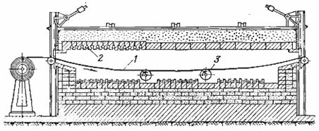
Rice. 9. Stretching belt furnace: 1 — heated belt, 2 — furnace heaters, 3 — supporting rollers.
High temperature furnace designs
The most common is the group of furnaces with carburund heaters. Carborundum heaters can operate up to 1450 ° C, therefore furnaces with carborundum heaters cover the range of 1200 — 1400 ° C. They differ from medium temperature furnaces with a thicker lining consisting of at least three layers.
Since the resistance of the rods changes significantly during heating and, moreover, to avoid their damage, a relatively slow heating to 850 ° C at reduced voltage is required, then high-temperature furnaces with carburund heaters are supplied with control transformers, which allow changing the supply voltage in small steps at least in a ratio of 2:1.
This is also necessary, since during operation the rods age, increasing their resistance, as a result of which it is necessary to increase the voltage supplied to it in order to maintain the previous power of the furnace.
Due to aging, which occurs with different intensity for individual rods, it is not recommended to connect them in series due to possible different changes in their resistance during heating.On the other hand, if one of the bars connected in parallel fails, it cannot be replaced with a new one, since the resistance of the other bars has already increased, it is necessary to replace them all with new ones, or take from old, already working bars, each with a resistance suitable for these conditions.
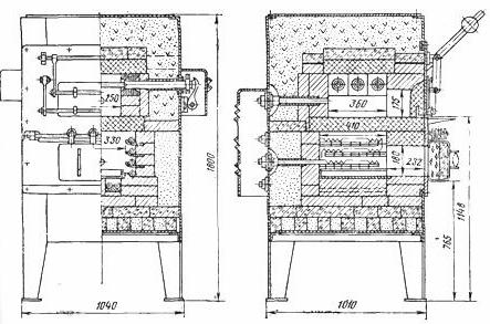
Rice. 10. Chamber high-temperature furnace. The lower chamber with metal heaters is used for heating, the upper one for high temperature with silicon carbide heaters.