Dial-up and cable connection to the equipment
One of the most important stages in the installation of equipment is its connection. The correctness of the operation of the installed equipment, the performance of its functions in the required volume and with the necessary parameters depend on the correctness of the work performed on the connection. In this article, we will consider basic methods of cable continuity, features of connecting the cable to the equipment.
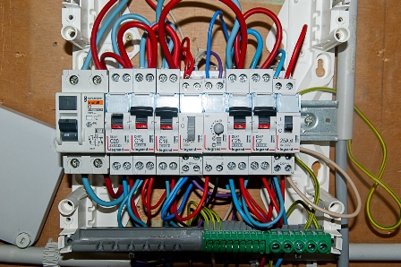
When carrying out work on the installation of new equipment, one of the stages of work is the laying of secondary switching circuits — cable and wire electrical conductors that connect various elements of the equipment. In this case, secondary switching circuits are cable lines that connect elements of electrical equipment with devices that control this equipment, protect it and perform various functions.
After all the circuits are laid, the tail goes directly to the continuity and connection of the cable between the equipment.
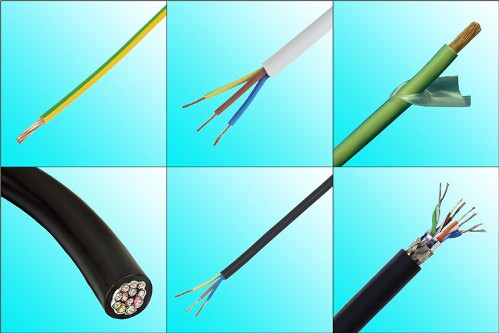
Basically, the concept of continuity means looking for the corresponding cores of a cable or wire at both ends.For example, paved control cable there are 12 cores, each of the cores must perform its own function. One or several incorrectly connected wires can lead to damage to the equipment or its incorrect operation during operation, when, if necessary, to perform a certain function, it will not be performed due to incorrect connection of circuits.
The process of ringing a cable may differ depending on local conditions and the type of cable itself. If there is only one cable line and all its cores are color-coded, then it will not be difficult to find the ends of each core - it is enough to connect the cable on both sides according to the color of the core. If there are several cables, but they are marked before the start of the installation, then during the connection there will also be no difficulties, since the cables are marked and the wires are color-coded.
The situation is complicated when the cables are not marked for one reason or another, and the wires are not color-coded, or several wires are color-coded. In this case, it is necessary to dial the inserted lines to identify all cores from both ends.
The process of winding the cable core can be done in several ways, depending on the distance between the ends of the ring wires. If we are talking about the continuity of the circuits in a distribution cabinet, protective panel, secondary circuits of the equipment, then the continuity can be done by yourself, with the help of a tester.
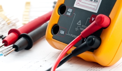
The multiset is used as a tester in continuity mode, and in the absence of such mode, in resistance measurement mode.It can also use a specially designed wire winding device, a low voltage indicator with a corresponding function, as well as a self-made battery, wires with probes of the required length, a lamp or a telephone headset.
It is also possible to use a megohmmeter for wire continuity, but this is quite dangerous and not applicable everywhere, since the megger operates at 500 V.
Continuity is related to integrity control. For example, a multimeter in continuity mode with one probe touching the cable core on one side of the cable and the other probe touching the core in series on the other side of the cable.
When the device shows the integrity of the core (corresponding readings or beep), it means that both ends of one core are found, they should be marked.
Marking of the core is done by hanging tags that are marked with a marker. When installing a large number of circuits, special sets of letters and numbers of different sizes can be used to mark them during continuity, which are worn on the marked wires in various combinations.
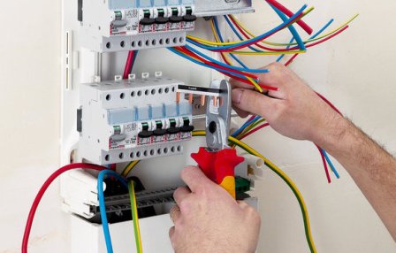
Usually, when a dial-up connection is made, the marked cable cores can be directly connected to the equipment. If it is a flexible wire, then before connecting, the ends of the wire must be finished with special tips.
If it is necessary to carry out a continuity test of a cable laid over long distances in different rooms, then this work is carried out together.In this case, for the continuity of the cable cores, the metal sheath of the cable or metal structures that are electrically connected to each other is used, or one of the cable cores, the ends of which are already found at both ends, for example, a marked core of another cable.
When dialing, the first worker is on one side of the cable, he connects one probe of the device (multiset or tester) to the metal sheath of the cable, a metal structure or to an already marked core, to these elements on the other side of the cable, the second worker connects one of the cores you want to ring ... The first worker alternately touches the cable cores with the second probe of the device, when the device shows integrity, the core is marked at both ends. In this way, all other wires are dialed.
There is another way to test cables — using a special transformer. A transformer with several output voltages is used for this purpose.
The common terminal of the transformer is connected to a deliberately marked core or to other elements that are connected electrically, the remaining terminals are connected to several wires that must be marked.
A voltmeter is taken at the other end of the cable and the voltage values between the core and the common conductor are measured in series.
For example, on one side the wires are connected to the terminals of the transformer with a voltage of 5, 10, 15, 20 V, which means that on the other side of the cable at the other ends of the same wires there should be the corresponding voltage values.
Cable phasing
Before connecting a three-phase high-voltage or low-voltage cable to the equipment, observe correct phase rotation… For example, if a bus section is fed by several cable lines, then when connecting all the cables it is necessary to ensure the correct position of the output phase so that there is no short circuit. Or after repairing the cable line (installing the cable sleeve) the phases at the other end of the cable may be in a different order.
Before applying voltage through this cable, it is necessary to "ring", that is, to make sure that the phase sequence is correct. This process is called step by step.
The phasing of the ends of the high-voltage cable with the equipment to which it is to be connected is carried out using special phasing voltage indicators. They are two voltage indicators connected to each other.
When phasing is performed, the cable is left unconnected, its ends are multiplied in such a way that it is safe to perform phasing, then voltage is applied through the cable and to the piece of equipment to which it is to be connected.
In addition, the directions between the veins and their connection points touch sequentially. If the pointer shows the presence of voltage, these are different phases. If the pointer shows no voltage, it means that the phasing of this core matches and can be connected to the equipment.
For phase cables with a voltage of up to 1000 V, conventional two-pole voltage indicators or a voltmeter designed for this voltage are used, and the voltage is also applied to the cable and the equipment to which this cable must be connected.
Alternately touching the wires and terminals of the equipment, we observe the readings of the voltage indicator or voltmeter, the presence of line voltage indicates that these are two different phases. If there are no readings, this indicates that these are points of the same potential, that is, the same phases, which means that they can be connected.