Schemes of complete transformer substations KTP
 A transformer substation (TP) is an electrical installation designed to convert voltage and distribute electrical energy to consumers. A factory-built substation is called a complete transformer substation (CTP).
Complete transformer substation - a substation consisting of transformers and blocks (switchgear or switchgear and other elements), delivered assembled or fully prepared for assembly. Complete transformer substations (hereinafter — KTP) or parts of them installed indoors refer to internal installations, installed outdoors — to external ones.
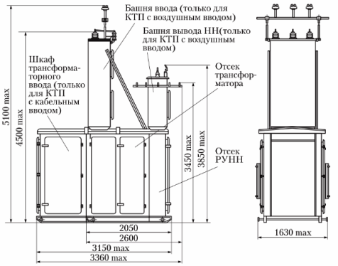
KTP with a capacity of 63 — 400 kVA of dead-end type with aerial (cable) HV input and LV aerial cable outputs and voltage 6 (10) kV
The construction of KTP includes a power transformer and a cabinet for high voltage and low voltage (0.38 / 0.22 kV).
Working substations, as a rule, do not have a switchgear on the side of the high-voltage cable, the power cable is connected to the transformer through a high-voltage bushing cabinet, which may contain a high-voltage switching device (load switch or disconnector), a protective device (fuse) and a block of busbars that form a supply circuit above 1 kV.
Blind connection (without switching device) is possible only for KTP radial power supply circuits, when switching on the high voltage switch of the power distribution device leads to disconnection / switching on of only one transformer. With mains and mixed power schemes A KTP switching device is required at the KTP input. The purpose of this switching device is to remove for repair the voltage to the output of the transformer and other circuit elements connected to this section of the busbar.
The LV switchgear is formed by a set of cabinets: low-voltage input cabinet / cabinets, sectional cabinet (for two KTP transformers), linear cabinets that contain appropriate switching devices (input, sectional, linear) — automatic switches or fuses with circuit breakers.
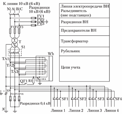
The electrical connections of the substation equipment and the connection of the outgoing lines to it are shown in fig. 1.
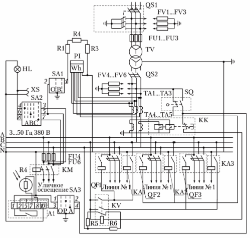
KTP scheme
The table shows the name and functional purpose of the KTP equipment.
Designation in the diagram Name and type of equipment Designation QS1 Disconnection point RP IV Activation and deactivation of KTP TV Transformer TM-160/10 Conversion of voltage 10 kV to voltage 0.38 / 0.22 kV FU1 — FU3 Fuse PK-10 Protection of the transformer from short-circuit currents FV1 — FV3 Arrests RVO-10, RVN-0.5 Protection of KTP from atmospheric overvoltage on lines with a voltage of 10 and 0.38 kV QS2 Switch R-3243 Shutdown of the low-voltage cabinet TA1 — TA5 Current transformer TK -20U3 Reduction of current for connection of electric meter and overload relay FU4 — FU6 Fuse E-27 Protection of street lighting lines from short circuit current KM Magnetic starter PME-200 Automatic switching on and off of street lighting P1 Counter SA4U Measurement of active power consumption R1 — R3 Resistor PE-50 Warming of the glucometer in cold weather SA1 Switch PKP-10 Turn on the heating of the counter SA2 Switch PKP-10 C for checking the presence of voltage and cabinet lighting HL Incandescent lamp Phase signal cabinet voltage and lighting SA3 PKP-10 switch Switch to automatic or manual street lighting control XS Print socket Connection of appliances and power tools SQ Limit switch VPK-2110 Interruption of 0.38 kV lines when the cabinet door is opened QC Thermorelay TRN-10 Transformer protection against overload currents QF1 — QF3 Automatic switches A3700 Switching on and off of 0.38 kV lines KA1 — KA3 Current Relay RE-571T Protection of 0.38 kV Lines Against Single-Phase Wire-to-Ground Faults Complete Pole-Mounted Transformer Substation (KTPS) is designed to receive, convert and electrically distribute power from 50 Hz three-phase alternating current in systems with a neutral earthed transformer neutral on the low voltage side of rural electricity networks.
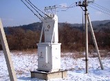
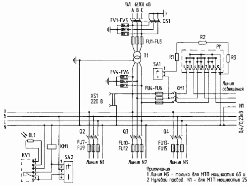
Pillar KTPS
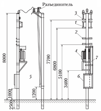
KTP pillar diagram
Complete transformer substations of the mast type are used to receive, transform and distribute three-phase alternating current with a frequency of 50 Hz with a nominal voltage of 6 (10) kV on the high voltage side and 0.4 kV on the low voltage side.
A complete mast-type transformer substation is used to power agricultural, residential, industrial and other facilities.
The KTP is connected to the power line through a disconnector, which is installed on the nearest support. Installation of KRUN low-voltage cabinets and high-voltage equipment in KTP is carried out in accordance with standard projects.
A disconnector is supplied complete with a mast type transformer substation, power transformer, limiters and fuses for high voltage. The schematic circuit diagram of the substation is shown in the figure.
KTP diagram of the mast
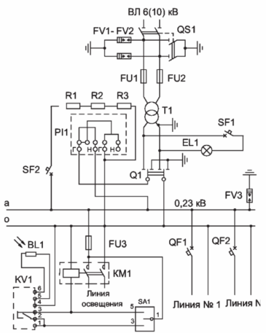
Scheme of a single-phase mast transformer substation