Short circuit in the supply circuits of electric arc furnaces
 Short network - a wire connecting an electric furnace transformer with electrodes. The short network includes:
-
Busbar… It is made of rectangular busbars, copper for large furnaces, aluminum for small ones. Connects the secondary terminals of an electric furnace transformer with fixed shoes.
-
Flexible cables. They form a loop that compensates for the movement of the posts when the electrodes move and the furnace tilts. Attached to removable shoes.
-
Pipes. Run along the sleeves of the racks. Supply current to the electrode holders.
The short network must:
1) have minimal electrical losses;
2) ensure uniform distribution of power on the phases;
3) have the lowest possible inductance, i.e. the highest possible power factor.
4) have minimal material costs.
The listed requirements for a short network must be optimized as many points are interconnected. For example, points 1 and 4 contradict each other.
The main parameters to consider when designing a short network are: inductance and phase load uniformity.
The inductance of a short network occurs due to the flow of alternating current through the current conductors of the phases that are located in one line. Therefore, their mutual inductances are not equal, as a result of which, with equal currents in the phases, the strengths of the individual arcs are different. This contributes to the destruction of the lining of the furnace located opposite the more powerful arc.
Mutual inductances can be greatly reduced if the current conductors are arranged so that the currents in them are directed in opposite directions at all times. However, in this case, the uniformity of the load of the phases may be disturbed. which can be dynamic or static. The first is due to the random nature of the change in the lengths of the arcs and their resistances and can be eliminated with the help of a system for automatically adjusting the furnace's operating mode. The second arises as a result of the geometric asymmetry of the current conductors.
The considered parameters of a short network very often contradict each other. In this regard, there are specially designed schemes of short networks with optimal parameter ratios.
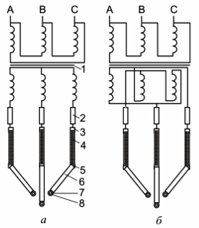
Rice. 1. Scheme of a short network of an arc steel furnace with connection of current wires: a — in a star of electrodes; b — in a triangle of the terminals of the secondary windings of the transformer of the electric furnace.
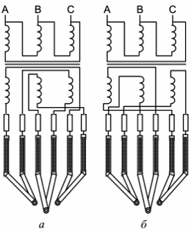
Rice. 2. Scheme of a short network of an arc steel furnace with a delta connection of current wires on the electrodes: a — symmetrical; b — asymmetric
In fig. Figures 1, 2 show optimized short network connections.The numbers on the diagrams indicate: 1 — electric furnace transformer; 2 — tires; 3 — fixed shoes; 4 cables; 5 — removable shoes; 6-tube tires; 7 - electrode holders, 8 - electrodes.
In fig. 1, and the secondary windings of the transformer are star-connected. The busbars, cables and pipes connected to them are grouped into phases and star-connected at the electrodes. The circuit is the simplest, but it has high inductance and low uniformity of charging, so it is used only for powering low-power furnaces.
In fig. 1, b, the secondary windings of the transformer of the electric furnace are included in a triangle with an adjacent location of the beginnings and ends. In such a connection, the buses with opposite currents are located next to each other, as a result of which the inductance of the buses, trying to extinguish each other si, is significantly lower than in the scheme shown in fig. 3.3, a.
In fig. 2, a shows a diagram of a short network with a symmetrical triangle on the electrodes, in which the forward and reverse currents flow side by side in the current conductors in all phases.
The mutual inductances in this circuit are much lower than in the circuits shown in Fig. 1, while the uniformity of the load of the phases is also ensured. However, in order to implement the scheme, the design of the furnace is significantly complicated, because with an increase in the number of cables, an additional fourth pole is required, moving synchronously with the first pole, which must withstand high dynamic loads.
This drawback is eliminated in the circuit with an asymmetric triangle on the electrodes, shown in fig. 2, b.In this circuit, the inductance is significantly reduced, but the uniformity of the phase load is significantly disturbed.
The optimum is the circuit, which is assembled in the same way as the scheme shown in fig. 1, and, only in it, after the busbar package, the flexible cables and pipes of the middle phase are raised relative to the end phases and form an equilateral triangle in cross section. Therefore, the mutual inductances of all phases are the same and high phase load uniformity is ensured. However, the scheme is structurally complex and the expediency of its use is justified only in high-power furnaces.
Parshin A.M.