What is the installed capacity
Installed power is the total rated electrical power of all electrical machines of the same type installed, for example, in a facility.
Installed capacity can mean both generated and consumed capacity in relation to generating or consuming enterprises and organizations, as well as to entire geographical regions or simply to individual industries. Rated can be taken as rated active power or apparent power.
In particular, in the field of energy, the installed power of an electrical installation is also called the maximum active power with which the electrical installation is able to work for a long time and without overload, in accordance with the technical documentation for it.

When designing electrical installations, the approximate total power of each of the users is determined, that is, the power consumed by different loads. This stage is necessary when designing a low-voltage installation.This allows you to agree on the consumption determined by the electricity supply contract for a specific facility, as well as determine the rated power of the high / low voltage transformer, taking into account the required load. The current load levels for the switchgear are determined.
This article is intended to help the reader orient himself, draw his attention to the relationship between total power and active power, to the possibility of improving power parameters using KRM, to various options for organizing lighting, and also to specifying the methods for calculating the installed capacity. Let's touch on the subject of inrush currents here.
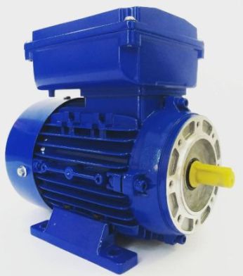
Thus, the nominal power Pn indicated on the motor nameplate means the mechanical power of the shaft, while the total power Pa differs from this value because it is related to the efficiency and the power of a specific device.
Pa = Pn /(ηcosφ)
To determine the total current Ia of a three-phase induction motor, use the following formula:
Ia = Pn /(3Ucosφ)
Here: Ia — total current in amperes; Pn — nominal power in kilowatts; Pa is the apparent power in kilovolt-amperes; U is the voltage between the phases of a three-phase motor; η — efficiency, that is, the ratio of the output mechanical power to the input power; cosφ is the ratio of active input power to apparent power.
The peak values of overtransient currents can be extremely high, typically 12-15 times the medieval value of Imn, and sometimes up to 25 times. Contactors, circuit breakers and thermal relays should be selected for high inrush currents.
The protection should not trip suddenly at start-up due to overcurrent, but as a result of transients the limit conditions for the switchgears are reached, due to which they may fail or not last long. To avoid such problems, the nominal parameters of the switchgear are selected slightly higher.
Today on the market you can find motors with high efficiency, but the inrush currents somehow remain significant. To reduce inrush currents, delta starters, soft starters as well variable drives… So the starting current can be halved, say instead of 8 amps 4 amps.
Quite often, in order to save electricity, the current supplied to the induction motor is reduced using capacitors, with reactive power compensation KRM… The power output is preserved and the load on the switchgear is reduced. Motor power factor (cosφ) increases with PFC.
The total input power decreases, the input current decreases and the voltage remains unchanged. For motors operating at reduced load for long periods, reactive power compensation is particularly important.
The current supplied to an engine equipped with a KRM installation is calculated by the formula:
I = I·(cos φ / cos φ ‘)
cos φ — power factor before compensation; cos φ '- power factor after compensation; Ia — starting current; I is the current after compensation.
For resistive loads, heaters, incandescent lamps, the current is calculated as follows:
for a three-phase circuit:
I = Pn /(√3U)
For a single-phase circuit:
I = Pn / U
U is the voltage between the terminals of the device.
The use of inert gases in incandescent lamps gives a more directed light, increases the light output and increases the service life. At the moment of switching on, the current briefly exceeds the nominal value.
For fluorescent lamps, the nominal power Pn indicated on the bulb does not include the power dissipated by the ballast. The current should be calculated using the following formula:
Aza = (Pn + Pballast)/(U·cosφ)
U is the voltage supplied to the lamp along with the ballast (choke).
Where power dissipation is not specified on the ballast choke, then approximately this can be considered 25% of nominal. The cos φ value, without the KRM capacitor, is taken to be approximately 0.6; with capacitor — 0.86; for lamps with electronic ballast — 0.96.
Compact fluorescent lamps, very popular in recent years, are very economical, they can be found in public places, in bars, in corridors, in workshops. They replace incandescent bulbs. As with fluorescent lamps, it is important to consider the power factor. Their ballast is electronic, so cos φ is approximately 0.96.
For gas discharge lamps, in which an electric discharge works in a gas or vapor of a metallic compound, a significant ignition time is characteristic, at which time the current exceeds the nominal one approximately twice, but the exact value of the starting current depends on the power of the lamp and the manufacturer. It is important to remember that discharge lamps are sensitive to the supply voltage and if it drops below 70% the lamp may go out and after cooling it will take more than a minute to ignite. Sodium lamps have the best light output.
We hope that this short article will help you orient yourself when calculating the installed capacity, pay attention to the power factor values of your devices and aggregates, think about KRM and choose the equipment that is optimal for your purposes, while it is the most efficient and economical.