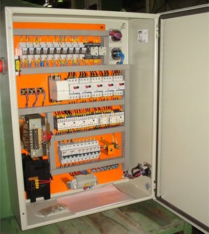
Procedure for testing electrical equipment of electrically driven metal cutting machines
The recommendations of this methodology apply to the testing of electrical equipment of metal and woodworking machines with electric drive. Currently, machines equipped with an electric drive are used in woodworking and metalworking. Machines perform different functions and have different purposes. Depending on the purpose, each machine can be equipped with a different number of mechanisms, drives and have different control schemes for these drives. Despite the difference in functionality, all machines should be periodically tested.
Test object
In accordance with the safety rules for working with tools and accessories, electrical machines, regardless of their complexity, purpose and field of application, must be periodically tested. These rules regulate the frequency of testing the electrical equipment of the machine, the insulation resistance and the continuity of the protective circuit.
The electric motors of the machine are in most cases controlled using starters (or using special intermediate relays). In rare cases, turning on and off the electric motor of the machine can be done directly through a protective device — a circuit breaker, a special button, etc. Such simple schemes are used rarely and usually on small machines.
In the case of the simplest machines, everything seems clear. For more complex machines, control is usually done via a separate, low-power transformer. Circuit separation and voltage reduction are used to ensure the safety of service personnel. The secondary windings of the control transformers must be earthed to the machine casing. In the most complex metal-cutting machines, several isolation transformers are used — for control circuits, signaling, power supply of semiconductor elements of monitoring and control circuits.
Based on the scheme of the machine, it is necessary to choose methods for testing electrical equipment. In any case, it is necessary to measure the insulation resistance of the power parts of the machine to ground, control circuits and signaling to ground. If an isolation transformer is used to power the control circuits, it is necessary to check the condition of the insulation between the power circuits and the supply circuits of the control and signal circuits.
When measuring insulation resistance with a megohmmeter, it is necessary to take measures against the failure of semiconductor elements in the control circuits - the semiconductor elements must be short-circuited.In addition to measuring the insulation resistance, it is necessary to test the power circuits and the control and signaling circuits with respect to ground with an alternating voltage of 1500 V for one minute. Signal-control circuits with a voltage below 50 V must also be tested if they do not contain semiconductor elements that can be damaged during the test.
The final stage of testing the electrical equipment of metal cutting machines is to check the metal connection between the metal parts of the machine. All metal parts on which electrical equipment is installed must have a reliable metal connection between each other and the ground wire (shielded PE wire). The check is carried out by visual inspection.
If you doubt the reliability of a continuous protective circuit, measure the resistance between the contact of the protective conductor and any metal part of the machine. The resistance of the metal connection in this case should be no more than 0.1 ohm. If the measurement of the metal connection is made directly to the PE wire and the contact connections of the machine body, then the resistance should be no more than 0.05 Ohm.
Certain characteristics
Insulation resistance
Measurement of the insulation resistance of the electrical equipment of metal-cutting machines is carried out before commissioning, after major repairs, and also once every six years. The insulation resistance must be at least 1MΩ.
Insulation resistance is measured:
-
power circuits to the machine body (PE-conductor),
-
control circuits relative to the machine body (PE-conductor),
-
signal circuits to the machine body (PE-conductor),
-
signal and control circuits versus power circuits (if these circuits are separated).
Control and signal circuits are considered to be separate from machine power circuits if these circuits are supplied by separate (separate) isolation transformers.
When measuring insulation resistance, the semiconductor elements in the measured circuits must be short-circuited to avoid damage.
AC voltage surge test
Power circuits, signal and control circuits must be tested with increased frequency voltage. The test frequency is the same as when measuring the insulation resistance of the electrical equipment of the machine. All circuits, with the exception of control circuits and signal circuits with a voltage below 50 V and containing electronic elements and semiconductor elements, must be tested with respect to the machine housing (PE-conductor). Test voltage — 1500 V, duration 1 min.
Checking the continuity of the protective circuit
The continuity check of the protective circuit is carried out by an external check. During the inspection, it is necessary to pay attention to the contacts between the metal parts of the machine, as well as to the quality of the PE-conductor connection with the housing. If, during a visual inspection, there are doubts about the quality of the contacts between open conductive parts, a resistance measurement must be made between the terminal of the PE wire and each metal part of the machine. The measured resistance should not exceed 0.1 Ohm.
Test and measurement conditions
The testing of electrical equipment of metal-cutting machines with an electric drive is carried out at a positive ambient temperature. If the machine has been placed in a warm room after being stored outdoors, especially at a low temperature, it should be kept indoors for a while until the condensation on the casing and electrical equipment disappears before testing. The duration of the warm-up of the machine is highly dependent on its size and is determined visually.
The humidity of the ambient air is important when conducting high voltage power circuits, control circuits and signaling of metal cutting machines, since condensation on the windings of electric motors and wires can lead to insulation failure and, accordingly, equipment failure (as tested, so and tested) ) …
Before performing high voltage tests, the equipment must be cleaned of dust, dirt and moisture. Atmospheric pressure has no particular effect on the quality of the tests performed, but is recorded for entering the data into the protocol.
Measuring tools
Insulation resistance measurement produces megameters for a voltage of 1000 V, for example M 4100/4, megohmmeters of the type ESO 202 can be used. The test with increased frequency voltage of the power is carried out using various installations, which consist of the following elements: test transformer, regulating device, control -measuring and protective equipment.
These devices include the installation AII-70, AID-70, as well as various high-voltage test transformers that have a sufficient level of protection and are properly prepared for testing.Ohmmeters are used to measure resistance: MMV, various multimeters, DC bridges. Accuracy class of devices — 4.
All devices must be inspected and test installations certified by the appropriate government agencies.
Test and measurement procedure
Insulation resistance measurement
As noted above, insulation resistance is measured using a megohmmeter with the machine completely off. The measurement is carried out in the following sequence:
1. Measure the insulation resistance after the motor control starter (or multiple motors) without disassembling the circuit. The megohmmeter is connected after the starter in the direction of the electric motor to one of the phases. A single measurement is made while all three phases are checked simultaneously across the motor winding.
2. The insulation resistance of the control circuits is measured, for which a megohmmeter is connected to the secondary winding of the isolation transformer, after which the grounding is disconnected from these circuits. Insulation resistance is measured — while all circuits are checked simultaneously through the transformer winding; if the tested circuits contain electronic elements, it is necessary to take measures to prevent their damage (short circuit, disassembly of boards). If the isolation transformer has several windings with different voltages, all windings are checked simultaneously.
3. The insulation resistance of the power circuits of the machine is checked before the motor starter (electric motors — if there are several of them) for this, the measurement is carried out phase by phase, since the phases are separated here.A megohmmeter is connected in series to each phase after the power machine of the machine. If there are several additional ones after the main machine, they should be included (you can combine the circuits and make one measurement, but with complex machines it can be difficult to determine where the connection should be made, it is easier to make several measurements directly on the main machine terminals).
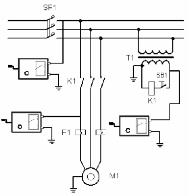
Scheme for measuring the insulation resistance of the electrical equipment of the machine
Testing the electrical equipment of the machine with increased voltage
To carry out high-voltage tests, it is necessary to combine the power circuits (place the jumpers in phases, as when measuring the insulation resistance before the motor starter), combine the power circuits with control and signal circuits. The ground from the control and signal circuits (on the secondary winding of the isolation transformer) must be removed.
Connect the test apparatus to the combination circuits and to the machine body. Apply tension and hold for 1 minute.
Checking the continuity of the protective circuit
Verification is done by visual inspection. An inspection of the metal parts of the machine is carried out - a reliable metal connection must be ensured between all metal parts of the machine. The quality of contact between parts of the equipment can be guaranteed in the absence of corrosion on metal parts, in the presence of bolted connections and, if necessary, in the presence of additional jumpers in the form of a copper wire with a cross section of at least 4 mm2.
If necessary (there are doubts about the quality of the contact), then the resistance is measured with an ohmmeter between the contact of the PE-conductor connection with the machine housing and any metal part of the machine.
Yansyukevich V.A.