Construction and operation of 0.38 kV overhead lines with insulated wires
Purpose and arrangement of 0.38 kV overhead lines with insulated conductors (SIP)
Overhead power lines with a voltage of 0.38 kV with insulated conductors (VLI 0.38) made using self-supporting insulated conductors (SIP) see electrical installations with a voltage of up to 1 kV with a solidly grounded neutral.
The reliability of VLI compared to the overhead line is increased due to the lack of glass linear insulation, as well as the consequences of climatic influences: the collision of wires is excluded, both under the direct influence of wind and ice, and due to the touch of tree branches; wire breaks are practically excluded due to the use of insulated wires with increased mechanical strength; no stopping due to throwing various objects on the wires.
VLI operation 0.38 is largely simplified and cheaper due to its constructive implementation. Essentially increased electrical safety both the service personnel and the population due to the lack of exposed live parts.Facilitates the ability to perform work (including connecting new users) on VLI 0.38 without removing voltage with minimal use of special protective devices. During the construction of the VLI, as well as the replacement of wires with insulated ones on existing lines, it is necessary to provide for the introduction of insulated wires into the premises. In this case, the work on replacing the bushings is included in the design and accounting documentation.
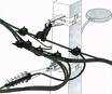
 By design, self-supporting insulated conductors (SIP) refer to insulated, unprotected conductors. The self-supporting insulated wire consists of an uninsulated or insulated carrier wire used as a neutral wire and several insulated wires wound on it - phase and street lighting. In the sections of the joint suspension of several VLIs on the self-supporting insulating wire near the support, labels indicating the number of the line dispatcher are fixed. Labels and labels on them must be weatherproof. In order to determine the phases when connected to the consumer line, the self-supporting insulated wires must have the factory marking of the phase wires and street lighting wires along the entire length (step 0.5 m). It is forbidden to install wires on overhead lines with insulated wires at an air temperature below -10 ° C.
Load capacity 0.38 kV overhead lines with insulated conductors (SIP)
The long-term permissible heating temperature of current-carrying conductors should not exceed 70 ° C for conductors insulated with thermoplastic polyethylene and 90 ° C for conductors insulated with XLPE.
The long-term permissible current loads of the wires depend on their cross-section, ambient temperature and the intensity of solar radiation.
The short-term permissible temperature of the core during a short circuit should not exceed 130 ° C for wires with thermoplastic insulation and 250 ° C for wires with XLPE insulation. In case of uneven load on the phases of the line, it is checked for long-term permissible currents for the most loaded phase.
The measurement of VLI loads shall be carried out annually at the maximum loads according to the schedule approved by the Chief Engineer of RES. The value of the long-term permissible load on the line and the results of the measurements must be stored in the VLI passport. Grounding of overhead lines 0.38 kV with insulated conductors
To ensure the normal operation of electrical receivers at the standardized level Electrical safety and VLI atmospheric overvoltage protection, earthing devices must be made.
Earthing from lightning protection is carried out: on supports after 120 m; on supports with branches to the entrances of premises where a large number of people can be concentrated (schools, nurseries, hospitals, etc.) or of great economic value (livestock premises, warehouses, workshops, etc.); on end supports with branches to the entrances; 50 m from the end of the line, as a rule, on the penultimate support; on supports at the intersection with overhead lines of higher voltage.
Re-grounding of the neutral conductor for overhead lines with insulated conductors is carried out as for HV 0.38 kV on wooden and reinforced concrete supports.
The resistance of the re-earthing switch depends on the soil resistance p and the number of earthing switches on the line.
The total resistance of the current spread of linear grounded electrodes (including natural ones) at any time of the year should be no more than 10 ohms.
Earthing conductors for multiple and lightning protection earthing must be made of round steel or wire with a diameter of at least 6 mm. When using non-galvanized earthing conductors, it is necessary to provide measures for their protection against corrosion.
Housings of street lighting fixtures, boxes, shields and cabinets, as well as all metal structures of supports must be neutralized. On reinforced concrete supports, for communication with the grounded electrode, you must use the reinforcement of the racks and supports (if any). On wooden supports (structures), the fixing armature of the circumference is not grounded, with the exception of supports on which multiple or lightning protection grounding of the neutral wire is made.
Acceptance of overhead lines with self-supporting insulated conductors
The acceptance of overhead lines with insulated wires for operation is carried out in accordance with the requirements of the rules for acceptance into operation of completed construction of facilities of the distribution network with a voltage of 0.38-20 kV. Any overhead line with insulated conductors put into service must be subjected to acceptance tests in accordance with the requirements of PUE.
The range of tests includes:
1.Selective (2-15% of the total) quality check of contact and connecting fittings on connections and branches of phase wires and VLI street lighting wires. The quality check of all connections of the supporting core of the self-supporting insulated conductor must be carried out by external inspection and measurement of the electrical resistance of the contact.
The compressed connections of the zero-bearing core of the self-supporting insulated wire are rejected if: the geometric dimensions (length and diameter of the compressed part) do not meet the requirements of the instructions for the installation of the connecting brackets; the curvature of the compressed bracket exceeds 3% of its length; there are cracks and traces of mechanical damage on the surface of the connecting bracket. If electrical resistance when the connecting section differs by more than 20% from the resistance in the entire section of the wire of the same length, the contact is also rejected.
2. Control of the marking of wires in connecting and branching clamps.
3. Measurement of the insulation resistance of the cores of the self-supporting insulated conductor. It is carried out with a 1000 V megometer between phase wires, phase wires and street lighting wires, neutral wire and all wires. The resistance value must be at least 0.5 MΩ.
4. Line insulation surge test. It is carried out with a 2500 V megohmmeter in the volume specified in paragraph 3 above, until the insulation resistance value is standardized. The VLI is considered to have passed the test if there is no insulation failure. After testing to remove the charging current, all VLI wires should be grounded briefly.
5.Inspection of grounding devices includes:
— checking the elements of grounding devices within the accessible limits, paying attention to the cross-section of the wires, the quality of welding and bolted connections; control of the presence of a circuit between grounding electrodes and grounded elements; measurement of resistances of grounded electrodes;
— measurement of the total resistance of all grounding wires of the neutral working wire VLI; measuring the current of a single-phase short circuit to the neutral conductor or the impedance of the "phase-neutral" loop with subsequent calculation of the current of a single-phase circuit.
6. Checking self-supporting insulated wire (SIP) sag and dimensions. If, upon acceptance of the VLI into operation, there is a violation of the requirements for its construction and installation, specified in paragraphs. 5 and 6, then this line should not be put into service.
List of documentation submitted for acceptance of overhead lines with self-supporting insulated conductors
The list of documentation presented upon VLI acceptance into operation and handed over to the client by the contractor includes:
- line project corrected and agreed with the customer (executive network diagram); executive drawing of the route, made on a scale of 1: 500;
- VLI route approval materials;
- factory test report (certificate) for self-supporting insulated wire;
- acts on the condition of self-supporting insulated wire on drums;
- certificates for linear fittings and supports;
- hidden works verification certificates;
- insulation resistance measurement protocol;
- protection settings, protocols for setting switching and line protection devices (circuit breakers, fuses, zero protection relays, etc.);
- protocol for measuring single-phase short-circuit currents at the end of the line or the resistance of the "phase-" zero "loop with an indication of short-circuit currents;
- grounding device test protocol;
- acts of acceptance of transitions and intersections.
Organization of the operation of overhead lines with insulated self-supporting wires
 The organization of operation of overhead lines with insulated wires 0.38 kV is carried out similarly to traditional overhead lines 0.38 kV with bare wires, taking into account the design features of VLI. To assess the condition of VLIs during operation, as well as to ensure their operability, personnel perform periodic inspections, tests and repairs in accordance with this PTE.
VLI reviews
Inspections of VLI tracks by installers must be carried out according to the approved schedule at least once a year. The engineering and technical staff conducts annual random checks on lines or sections, as well as on all lines undergoing major repairs in the current year.
Personnel conducting the inspection of VLI routes must: inspect the entire VLI route; check the condition of a self-supporting insulating wire from the ground along the entire route; inspect the intersection of the VLI with power lines, communications and other engineering structures, if necessary, determine the compliance of the dimensions with the VLI; determine the compliance of the dimensions of the VLI to the ground and the sag arrows of the self-supporting insulated wire of the design values in questionable places; visually determine the condition of the support racks; identify the presence of trees along the route, the fall of which can lead to mechanical damage to the self-supporting insulated wire; check from the ground the state of attachment of the non-existent core of the self-supporting insulated wire in the tension brackets of the anchor-type supports and in the bearing brackets of the intermediate supports; inspect from the ground the condition of the armature on the branches to the entrances of the buildings; check the connection of the lower ground outlet of the rack to the ground wire when they are connected above ground. If necessary, horse inspections are carried out with spot checks. The analysis of the data obtained during the inspection is carried out by the staff, comparing it with the standard parameters and the results of previous inspections, while determining the degree of danger of defects and outlining the deadlines for their elimination.
Frequency of VLI tests
The VLI must be tested before commissioning as well as during operation.The frequency of tests during operation is determined: first — one year after the lines are put into operation; subsequent — — if necessary (after repair, reconstruction, connection of new loads, etc.); some types of tests — with the frequency indicated below.
Preventive tests of the insulation of the VLI with a megohmmeter at a voltage of 2500 V are carried out as necessary, but at least once every 6 years. Tests are performed after disconnection (disconnection) from the line of all users. Insulation tests of self-supporting insulated wires, insulation of their connections and branches from them are carried out as necessary, but at least once every 6 years. The measurement of the total resistance of all grounding conductors of the neutral conductor, as well as individual grounding conductors at supports with external slopes with bolted connections accessible from the ground, is carried out at least once every 6 years. Measurements should be carried out during periods of maximum soil drying.
Selective control of the state of grounded electrodes with their excavation is carried out selectively on 2% reinforced concrete supports at the places of their possible damage, in aggressive soils, in populated areas with resistance measurements at least once every 12 years. Visual control the presence of a circuit between grounding conductors and grounded elements is carried out annually when inspecting overhead lines with insulated conductors. The measurement of the single-phase short-circuit current to the neutral conductor is carried out when the length or cross-section of the VLI conductors (or its sections) changes, but at least once every 12 years. The results of the test are documented in a report and entered in the passage of the line.
Look for faults on overhead lines with insulated wires
Searching for faults in the insulation of self-supporting insulating wire (SIP) is performed to determine the core with damaged insulation and the location of the fault.
Determining damaged cores is done by testing the insulation of each current-carrying core against the neutral conductor and between the current-carrying cores. Tests are carried out with a 2.5 kV megometer after disconnection (disconnection) from the line of all consumers.
The methods for determining the fault locations of VLI 0.38 are the same as for cable lines. The pulse method is used to determine the damage zone, and the damage locations are induction and acoustic methods. After testing the self-supporting insulated conductor, all conductors must be grounded briefly to remove the charging current.
Repair of overhead lines with insulated wires
Current and major repairs are carried out to maintain the line in a technically sound condition. Repair of the VLI must be carried out according to the approved schedule, drawn up taking into account the results of inspections and tests. The frequency of major repairs for VLI on reinforced concrete poles is 1 time in 10 years, on wooden poles — 1 time in 5 years. The scope of repair is determined based on defects found during VLI inspections and tests.
The scope of overhaul, if necessary, includes: replacement and repair of struts; replacement of supporting parts; alignment of supports; installation of attachments to existing supports; replacement of self-supporting insulated wire; adjusting the drooping arrows of the wires; replacement of input data for users; street lighting repair and other types of works. Repair of grounding devices and grounding slopes is carried out without delay.
If a self-supporting insulated wire breaks as a result of a falling tree, a vehicle collision, or other causes, the repair must be accomplished by installing a self-supporting insulated wire repair insert. In this case, the cross-section of the core of the repair insert must be no less than the cross-section of the damaged cores.
The repair insert is installed as follows. The neutral bearing core of the self-supporting insulated wire is connected using oval connectors of the CO AC brand, which are installed by crimping. The phase and lantern wires are connected by connecting or branch clamps, which must be located along the length of the self-supporting insulated conductor.
When phasing a self-supporting insulated conductor, the existing factory phase marking should be used. The restoration of the insulation of wires in case of minor damage to it is carried out with a self-adhesive tape such as SZLA, LETSAR LP, LETSAR LPm, used in the installation of cable lines.