How to check if the meter is turned on correctly with an existing connection
Checking the correct connection of measuring devices in installations above 1000 V
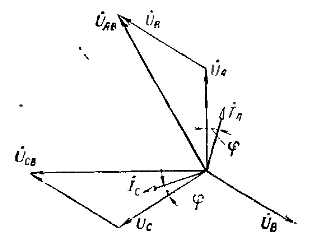
It is possible to conclude that the glucometer is turned on correctly if the vector diagram taken at its terminals coincides with the normal one. The necessary and sufficient conditions for this are, firstly, the correct execution of the secondary circuits of the voltage transformer and the connection of the parallel windings of the meter to them, and, secondly, the correct execution of the secondary circuits of the current transformer and the connection of the series windings of the meter to them .

Vector diagram of a three-phase two-element meter with an inductive load
So, checking the correctness of the inclusion of measuring devices consists of two stages: checking the voltage circuits and current circuits (removing the vector diagram). Checking the secondary circuits of the voltage transformer. This check consists of checking the correctness of the phase marking and checking the condition of the voltage circuits.
The check is performed at operating voltage. All line voltages and voltages of each phase to ground are measured. It is obvious that in working circuits all voltages in the network are equal and amount to 100 — 110 V.
The values of the voltages between the phase and the "earth" depend on the connection circuit of the voltage transformer and the performance of the secondary circuits. If two single-phase voltage transformers are connected in open delta or applied three-phase transformer voltage with an earthed phase, then the voltage of this phase relative to «ground» is equal to 0, and of the other phases it is equal to linear.
If the neutral of the secondary winding is grounded in a three-phase voltage transformer, then the voltages of all phases relative to "ground" will be about 58 V.
Checking the correctness of the phase names starts with finding the phase B to connect to the middle terminal of the meter. In the first case, it is easy to find it by measuring the voltage with respect to «ground». In the second case, you can proceed as follows.
The voltage transformer is disconnected on both sides. After checking the absence of voltage and taking all necessary safety measures on the high voltage side, remove the fuse from the middle phase.
The voltage transformer is commissioned. Secondary line voltages are measured. The line voltages of the disconnected phase will be reduced (approximately by half), while the voltage between the disconnected phases will not change. The phase found is connected to the middle terminal of the voltage circuits of the meter, and the other two to the end terminals, according to the marking.
Then, after disconnecting the voltage transformer again and taking safety measures, the fuse is reinstalled, after which the voltage transformer is put into operation.
The remaining phases in all cases can be determined using a phase indicator, which is designed to determine the order of rotation of the phases in a three-phase network. This device is a miniature three-phase induction motor with a push-button switch. It uses a disc of light metal with contrasting sectors as a rotor. The device is intended for short-term operation (up to 5.s).
To check, the marked terminals of the phase indicator are connected in the same order as that of the counter to the terminals of the voltage coils of the counter, and by pressing the button, the direction of rotation of the disk is observed. Rotating the dial in the direction of the arrow indicates the correct marking and, accordingly, the correct connection of the voltage windings. Otherwise, it is necessary to identify one of the possible causes of the reverse phase rotation: incorrect marking (phase colors) of the primary circuits or an error in the implementation of the secondary circuits of the voltage transformer.
To identify the causes of reverse phase rotation, check the phase rotation of the terminal closest to the voltage transformer and repeat the continuity of the voltage circuits. After correcting the error (reconnecting the «end» phases in the primary circuits or in the voltage transformer circuits), the phase sequence check is repeated.
Determining the correctness of the marking is greatly simplified if other measuring instruments or relay protection devices are fed from this voltage transformer with deliberately verified correct connection. Then it is enough to phase the checked counter with them.
Consider some of the errors and malfunctions found when testing voltage circuits. Blown fuses or tripping of a circuit breaker due to a short circuit in the secondary circuits most often occurs due to incorrect connection of the voltage circuits to the terminals of series windings.
The reduction or absence of voltage in the network can be caused by various reasons: broken wire or blown fuse, malfunction of the voltage transformer, connection to two terminals of the same phase. The specific cause is revealed by additional checks after disconnecting the voltage transformer.
If, when measuring line voltage, one of them, usually between the end terminals, is about 173 V, this means that the secondary winding of one voltage transformer is reversed with respect to the secondary winding of the second transformer.
After correcting the circuit errors and troubleshooting, all measurements are repeated.
Checking the secondary circuits of current transformers
If the wires of the two final voltage circuits are interchanged at the terminal box, then with a symmetrical load, the disc of a properly connected active energy meter should stop (a small movement in each direction is possible). In the second method, the number of revolutions of the disk for measuring active energy is counted for a certain period of time (1 — 3 minutes).
Then the conductor of the middle phase of the voltage circuit is disconnected and the number of revolutions of the disk is counted again for the same period of time. If the counter is turned on correctly, the number of revolutions will be reduced by half.
Checking the correct connection of measuring devices in installations below 1000 V
 If the glucometer is turned on correctly, in any case the conjugation of the same phases of current and voltage in each rotating element is ensured.
When checking the correct inclusion of the counter, phase and line voltage, and the phase rotation order is also determined. If the alternation is reversed, any two rotating elements and the current transformers supplying them must switch each other.
Then, one by one, the correctness of the direction of rotation of the disk is checked when each element individually acts on the movable system. Checking is done by removing the terminal box jumpers one at a time until one rotary element remains in operation and the other two are taken out of operation. Disconnecting and connecting the jumpers is done only when the voltage is removed.
In another method, the connection is broken and an artificial single-phase load is briefly connected to each phase. It can serve as a resistance of 40 — 50 ohms with a power of 200 watts. If the counter is turned on correctly, then each of its elements will turn the dial to the right. Rotating the disc in the opposite direction indicates the current flow in the series winding in the opposite direction. To correct the error, it is necessary to replace the bridges of the wires connected to this element.
