Short-circuit current, which determines the magnitude of the short-circuit current
This article will focus on short circuits in electrical networks. We will consider typical examples of short circuits, methods of calculating short circuit currents, pay attention to the relationship between inductive resistance and the rated power of transformers when calculating short circuit currents, and also give specific simple formulas for these calculations.
When designing electrical installations, it is necessary to know the values of symmetrical short-circuit currents for different points of a three-phase circuit. The values of these critical symmetrical currents make it possible to calculate the parameters of cables, switchgear, selective protection devices etc.
Next, consider a three-phase zero-resistance short-circuit current fed through a typical distribution step-down transformer. Under normal conditions, this type of damage (short circuit of the bolt connection) is the most dangerous and the calculation is very simple.Simple calculations allow, subject to certain rules, to obtain sufficiently accurate results that are acceptable for the design of electrical installations.
Short-circuit current in the secondary winding of a step-down distribution transformer. As a first approximation, the resistance of the high voltage circuit is assumed to be very small and therefore can be neglected:
Here P is the rated power in volt-amperes, U2 is the phase-to-phase voltage of the secondary winding without load, In is the rated current in amperes, Isc is the short-circuit current in amperes, Usc is the short-circuit voltage in percent.
The table below shows typical short-circuit voltages for three-phase transformers for a 20 kV HV winding.
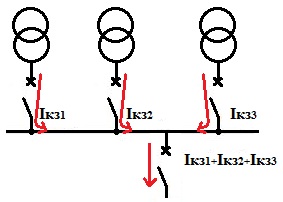
If, for example, we consider the case when several transformers are fed in parallel to the bus, then the value of the short-circuit current at the beginning of the line connected to the bus can be taken equal to the sum of short-circuit currents, which are previously calculated separately for each of the transformers.
When all transformers are fed from the same high voltage network, the values of the short-circuit currents, when summed, will give a slightly higher value than they actually appear. The resistance of the busbars and switches is neglected.
Let the transformer have a rated power of 400 kVA, the voltage of the secondary winding is 420 V, then if we take Usc = 4%, then:
The figure below provides an explanation for this example.
The accuracy of the value obtained will be sufficient to calculate the electrical installation.
Three-phase short-circuit current at any installation point on the low voltage side:

Here: U2 is the no-load voltage between the phases of the secondary windings of the transformer. Zt — impedance of the circuit located above the point of failure. Then consider how to find Zt.
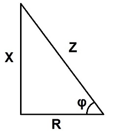
Each part of the installation, be it a network, a power cable, the transformer itself, a circuit breaker or a busbar, has its own impedance Z consisting of active R and reactive X.
Capacitive resistance does not play a role here. Z, R and X are expressed in ohms and calculated as the sides of a right triangle as shown in the figure below. Impedance is calculated according to the right triangle rule.
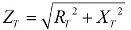
The grid is divided into separate sections to find X and R for each section so that the calculation is convenient. For a series circuit, the resistance values are simply added and the result is Xt and RT. The total resistance Zt is determined by the Pythagorean theorem for a right triangle by the formula:
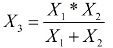
When the sections are connected in parallel, the calculation is carried out as for resistors connected in parallel, if the combined parallel sections have reactance or active resistance, the equivalent total resistance will be obtained:
Xt does not account for the influence of inductances, and if adjacent inductances influence each other, then the actual inductance will be higher. It should be noted that the calculation of Xz is only related to a separate independent circuit, that is, also without the influence of mutual inductance. If the parallel circuits are located close to each other, then the resistance Xs will be noticeably higher.
Consider now the network connected to the input of the step-down transformer. The three-phase short-circuit current Isc or short-circuit power Psc is determined by the electricity supplier, but based on these data the total equivalent resistance can be found. Equivalent impedance, which simultaneously results in the equivalent for the low voltage side:

Psc-three-phase short-circuit supply, U2-no-load voltage of the low-voltage circuit.
As a rule, the active component of the resistance of a high-voltage network — Ra — is very small and, compared to the inductive resistance, insignificant. Conventionally, Xa is taken equal to 99.5% of Za and Ra is equal to 10% of Xa. The table below shows approximate figures for these values for 500 MVA and 250 MVA transformers.
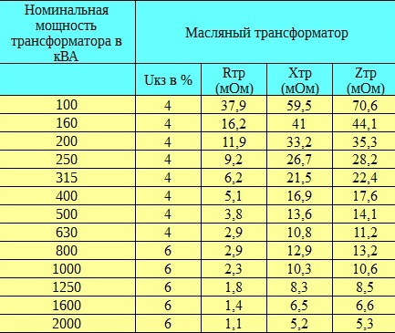
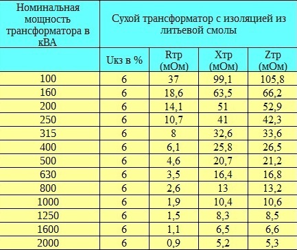
Full Ztr — Low Voltage Side Transformer Resistance:
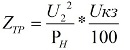
Pn — rated power of the transformer in kilovolt-amperes.
The active resistance of the windings is based on power losses.
When performing approximate calculations, Rtr is neglected and Ztr = Xtr.
If a low-voltage circuit breaker is to be considered, the impedance of the circuit breaker above the short-circuit point is considered. The inductive resistance is taken equal to 0.00015 Ohm per switch and the active component is neglected.
As for the busbars, their active resistance is negligibly small, while the reactive component is distributed at approximately 0.00015 Ohm per meter of their length, and when the distance between the busbars is doubled, their reactance increases by only 10%. Cable parameters are specified by their manufacturers.
As for a three-phase motor, at the moment of short circuit it goes into generator mode, and the short circuit current in the windings is estimated as Isc = 3.5 * In. In single-phase motors, the increase in current at the moment of short circuit is negligible.
The arc that usually accompanies a short circuit has a resistance that is by no means constant, but its average value is extremely low, but the voltage drop across the arc is small, therefore the current practically decreases by about 20%, which facilitates the operation of the circuit breaker without disturbing its operation without particularly affecting the tripping current.
The short-circuit current at the receiving end of the line is related to the short-circuit current at the supplying end of the line, but the cross-section and material of the transmitting wires, as well as their length, are also taken into account. Having an idea of resistance, anyone can do this simple calculation. We hope that our article was useful for you.