Measurement of the resistance of the phase to zero of the loop
 In accordance with PTEEP, in order to control the sensitivity of the protection to single-phase earth faults in installations up to 1000 V with earthed neutral, it is necessary to measure the resistance of the "phase zero" loop.
To measure the resistance of the "phase-zero" circuit, there are a number of devices that differ in circuits, accuracy, etc. The application areas of various devices are given in the table. 1.
Instruments for measuring the electrical parameters of earthing devices, including measuring the phase-zero resistance of the loop
Device type or method Measured parameter Note M-417 Loop resistance with subsequent calculation of single-phase fault current Range - control ECO-200 Single-phase earth fault current Range - control EKZ-01 Single-phase earth fault current Range - control Ammeter + voltmeter Voltage and current High accuracy (application area - measurements)
The check is carried out for the most distant and most powerful electrical receivers, but not less than 10% of their total number.
The check can be carried out by calculation according to the formula Zpet = Zp + Zt / 3, where Zp is the total resistance of the conductors of the phase-zero loop; Zt is the impedance of the supply transformer. For aluminum and copper wires Zpet = 0.6 Ohm / km.
According to Zpet, the current of a single-phase short-circuit to the ground is determined: Ik = Uph / Zpet If the calculation shows that the multiple of the current of a single-phase earth fault is 30% higher than the permissible multiplicity of operation of protective devices specified in Rules for Electrical Installation (PUE), then we can limit ourselves to the calculation. Otherwise, direct short-circuit current measurements must be made with special devices, for example, of types EKO-200, EKZ-01, or by using the ammeter-voltmeter method at low voltage.
Ammeter-voltmeter method for measuring the phase-zero resistance of the loop
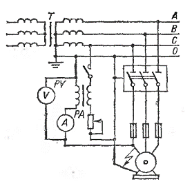
The electrical equipment under test is disconnected from the mains. The measurement is made on alternating current from a step-down transformer. For measurement, an artificial short circuit is made from a single-phase wire to the body of the electrical receiver. The test scheme is shown in the figure.

Scheme for measuring the resistance of the phase-neutral loop by the ammeter-voltmeter method.
After applying the voltage current I and voltage U, the measuring current must be at least 10 — 20 A. Resistance of the measured loop Zn = U / I. The resulting value of Zp must be arithmetically added to the calculated value of the impedance of one phase of the supply transformer Rt / 3.
Phase-Neutral Resistance Measurement Program
1.Acquaintance with the design and construction documentation and the results of previous tests and measurements.
2. Preparation of necessary electrical measuring instruments and test devices, wires and protective equipment.
3. After completion of the organizational and technical measures and admission to the facility, measurements and tests
4. Evaluation and processing of measurement and test results.
5. Recording of measurements and tests.
6. Correction of schemes, registration of signatures for the suitability (unsuitability) of electrical equipment for further operation.
