How the transformer substation 10 for 0.4 kV is arranged
The energy system consists of many structural elements, each of which performs its own function in the process of transferring electricity from power plants to the end user. Substations 10 for 0.4 kV carry out the last stage of electricity conversion: from these substations, electricity goes directly to the consumer - to settlements and industrial enterprises. Consider how the transformer substation 0.4 kV 10 is arranged.
There are several types of 10 / 0.4 kV substations, the design of which depends on their capacity, purpose and operating conditions.
Mast and pole substations
On the territory of small settlements, cottage cooperatives, mast and pole transformer substations are used to supply consumers with electricity.
The main advantage of these substations is their simplicity in design and ease of maintenance.
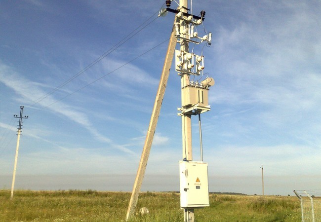
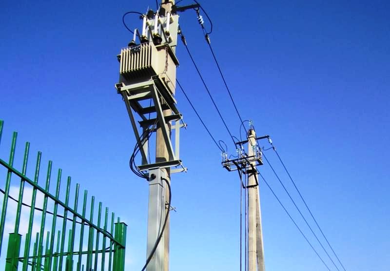
A pole transformer substation is installed directly on a linear support of a 10 kV overhead line (overhead line-6 kV) or on a separate stand (support) of the type SV-105, SV-110, etc. The difference mast substation by installing it between two racks (supports).
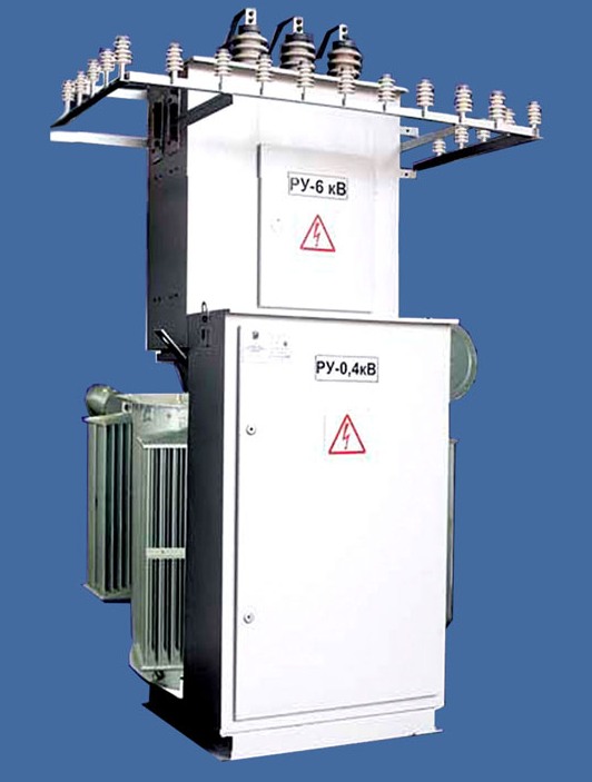
The pole (mast) substation is arranged as follows.
A mounting frame and a low-power transformer, typically in the 16-160 kVA range, are mounted directly on the support (rack).
Above the transformer, a frame is mounted with fasteners for high-voltage fuses of the PCT type, which are used to protect the transformer from overcurrent. From the fuses, wires go down to the high-voltage inputs of the power transformer, and wires go up to the power line.
To prevent a collision, the wires from the fuses to the overhead line are additionally attached to supporting insulators, which are mounted on a special traverse. Arresters or surge arresters (SPDs) are also mounted on the cross of the insulators to protect against atmospheric and switching surges in the mains.
A high voltage disconnector can be additionally mounted on the support to allow the voltage to be removed and to create a visible break in the electrical circuit. The disconnector is installed in the disconnection of the power wire from the air line on a separate frame. The disconnector drive is located at the bottom of the support and is connected by a shaft to the disconnector. The handle of the device is removable, and the device itself is fixed with a lock to prevent unauthorized persons from carrying out operations.
A low voltage 0.4 kV cabinet is installed under the power transformer. This cabinet is connected to the low-voltage inputs of the transformer, switching and protective devices - circuit breakers and fuses or circuit breakers - are installed in it, and the consumer cable is also connected.
Depending on the number of users and the size of the load, there may be several outgoing lines, each of which is protected by a separate circuit breaker. If the consumers are supplied by an overhead power line, then surge arresters can be installed to protect against surges.
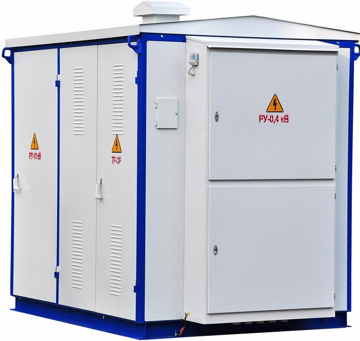
Complete Transformer Substations (KTP)
The next type is complete transformer substations. These are ready-made solutions that are supplied by manufacturers in assembled form or in separate blocks for further assembly at the installation site.
Depending on the capacity, the transformer substations can be manufactured in a metal or concrete enclosure or in a sandwich panel enclosure. Low-power substations are manufactured in a metal case, such KTPs are installed, as a rule, in rural areas. Also, KTPs of this type can be used to power consumers in temporary facilities (construction site, guard post, etc.).
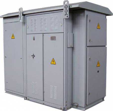
Structurally, metal KTPs have the same equipment as mast substations (poles), only all these elements are mounted inside the metal body of the KTP. The KTP itself is installed on a pre-assembled base or supports.
For convenience and safety during operation and maintenance of KTP, switching and protective devices of different voltages are installed in separate compartments with locking devices. Depending on the design of the KTP, the power transformer can be installed in a separate compartment or in an open way — in this case, a special metal protective case is installed over the transformer bushings.
The housing and metal parts of the KTP equipment must be grounded.Grounding is necessary to ensure safety when servicing the KTP, as well as to ensure the operation of the electrical network grounding system.
More powerful complete transformer substations in concrete housing or sandwich panels are usually installed in residential areas to supply several residential buildings or in an area with high load concentration.
See also: Advantages of complete transformer substations andSchemes of entire transformer substations
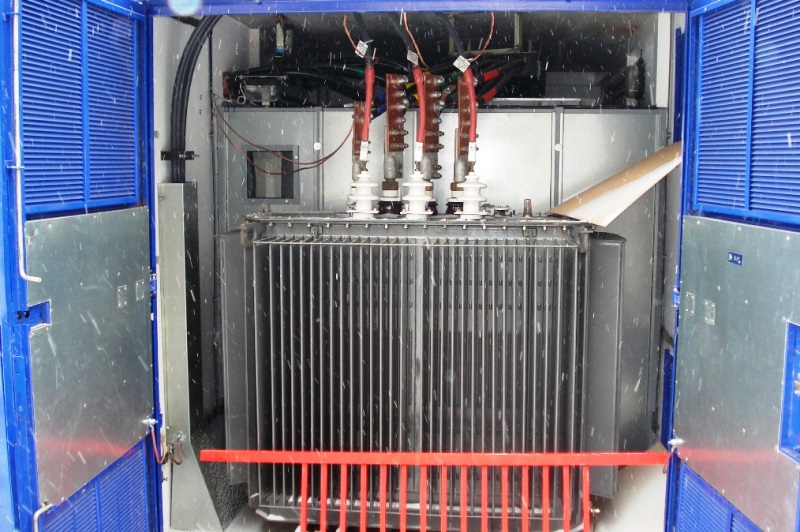
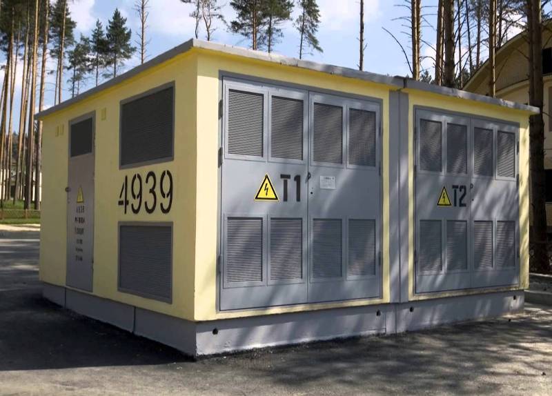
Transformer substation 10 / 0.4 kV in a special building
In addition to KTP, substations located in special buildings are often used to supply residential buildings and other groups of users. The 10 / 0.4 kV substation building is built according to the same type of design, taking into account the local conditions and the size of the user load.
One or more step-down power transformers with a capacity, as a rule, up to 1000 kVA can be installed in such a substation.
For safety and ease of maintenance, high and low voltage switchgear are located in separate rooms. The power transformer is also installed in a separate chamber.
In the 10 kV switchgear, high-voltage switches or fuses, as well as disconnectors or a retractable switchgear, are installed, which provide a visible gap for safety when servicing the transformer and circuit breaker.
On the low voltage side, an input circuit breaker is installed, as well as circuit breakers for outgoing consumer lines. For the safety of maintenance of 0.4 kV lines, it is also necessary to provide a visible gap - for this circuit breakers are installed.
In order to protect the electrical network from overvoltages, limiters or surge arresters are installed on the HV and LV sides.
If voltage and load control is required, current and voltage transformers are installed on the high voltage side and current transformers on the 0.4 kV side.
Transformer substations in enterprises
In industrial enterprises, where a large number of 0.4 kV consumers are concentrated, 0.4 kV distribution devices are installed for the distribution of electricity in individual buildings or directly in production facilities. 0.4 kV switchgear can be implemented on one or several switchboards (panels), which are fed by one or two 10 / 0.4 kV transformers.
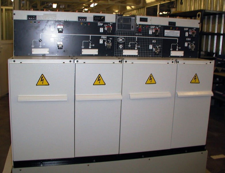
Two power supply units (transformers) are installed in case it is necessary to provide a reliable and uninterrupted power supply to the user. In this case, the switchgear is divided into two busbar sections, each of which is fed by a separate transformer. A motorized switch or contactor is installed between the sections, by turning on which voltage is supplied to one of the sections in the event of a power failure of one of the transformers.
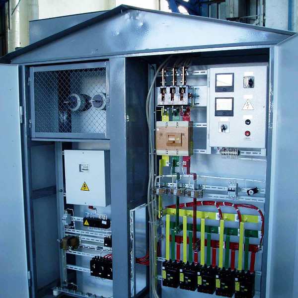
In this switchgear, in addition to automatic machines, group switches can be installed, designed for the convenience of servicing individual sections of the switchgear. To control the operation mode of the equipment, signal lamps, voltmeters, ammeters, measuring devices and, if necessary, measuring current transformers are installed on the panel.
Also, in 0.4 kV switchboards, various protection and automation systems can be additionally installed, for example, earth fault protection, automatic emergency lighting, etc.