How to check a thermoelectric pyrometer
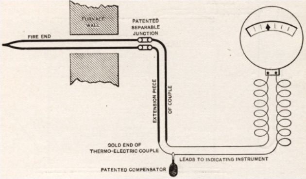
The thermoelectric pyrometer is a set that consists of from a thermoelectric converter (thermocouple), compensating and connecting wires connected to it and an indicating or recording measuring device. As such, either a portable or panel millivoltmeter or an automatic potentiometer can be used.
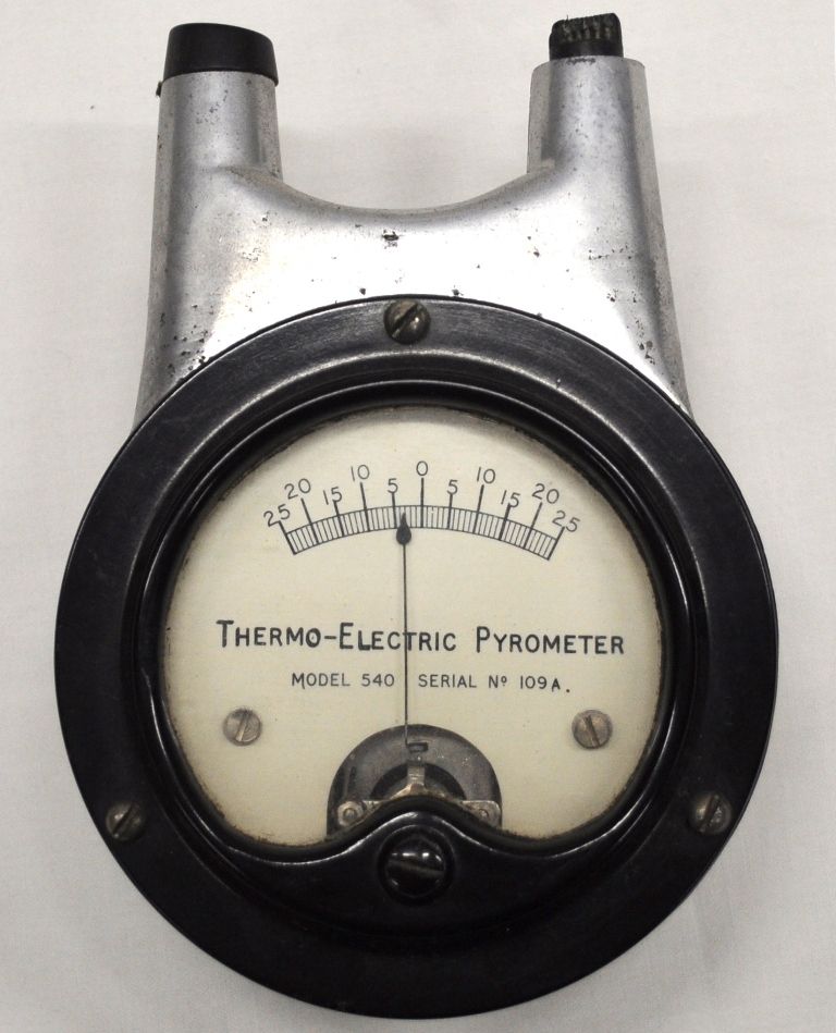
Antique thermoelectric pyrometer from 1910
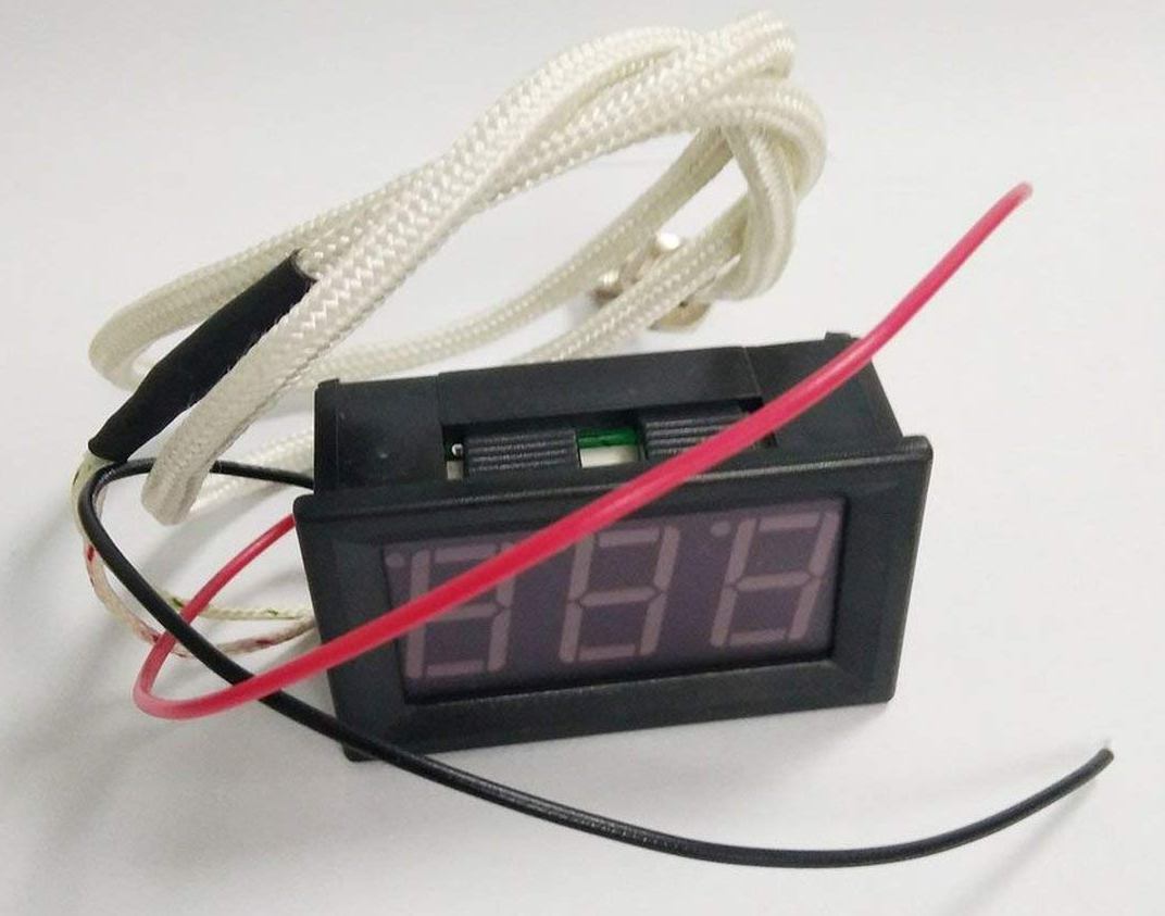
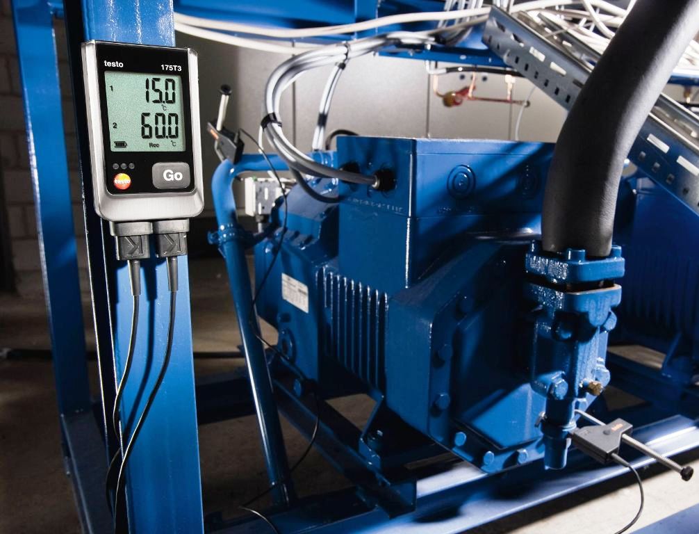
Modern digital thermoelectric pyrometer
If the millivoltmeter is used under operating conditions, the electrical resistance of the thermocouple, compensation and connecting wires to within ± 0.1 ohm must be equal to that indicated on the scale of the millivoltmeter magnitude R int.
The circuit resistance of the thermocouple is adjusted to the required value by means of a compensation coil connected in series with the thermocouple.
Checking the readings of a thermoelectric pyrometer is sometimes carried out in a complete set, without prior calibration of the thermocouple included in its composition.In this case, the thermocouple connected to the millivoltmeter or automatic potentiometer is placed with the reference thermocouple in a calibration oven.
If the temperature of the free ends of the thermocouple differs from 0 ° C, then when the circuit of the millivoltmeter is open, the corrector adjusts its arrow to the mark on the scale corresponding to the temperature of the free ends.
This operation is not necessary if a suitably calibrated automatic potentiometer or millivoltmeter equipped with a device for automatic correction of the temperature of the free ends of the thermocouple is used in the pyrometer set. In these cases, compensating wires must be brought to the terminals of the measuring device.
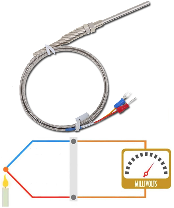
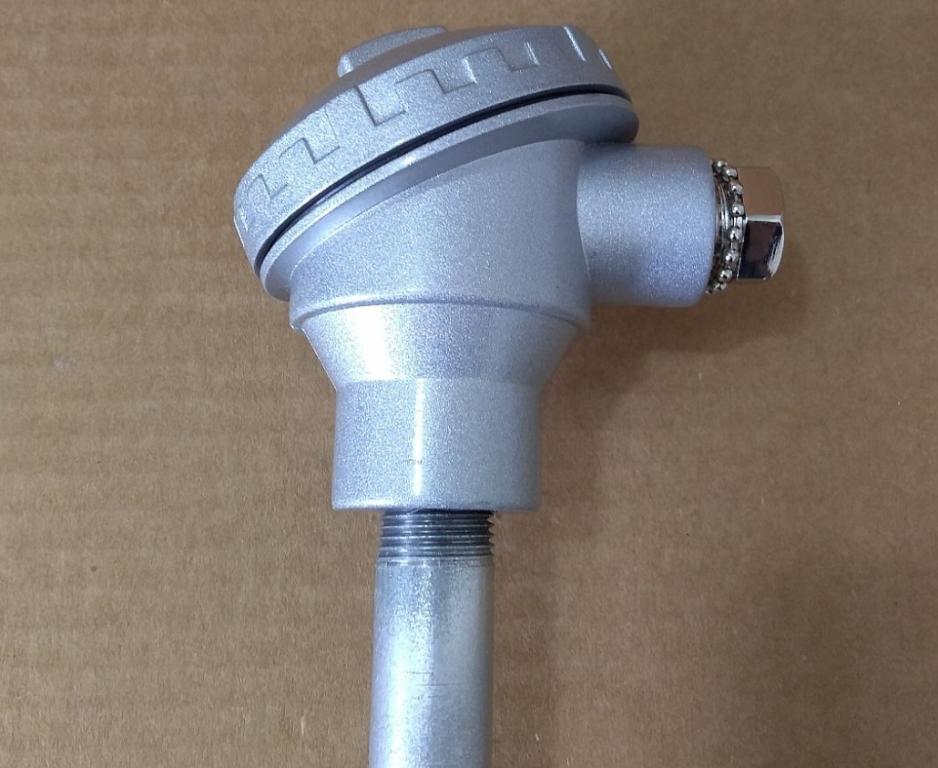
Thermocouple
By gradually increasing the current in the calibration oven using a reference thermocouple, oven temperatures are set one after the other through hundreds of degrees, stabilizing the oven at each temperature for several minutes.
The value of the temperature established in the furnace is determined by the thermo-EMF of a reference thermocouple read by a laboratory potentiometer, and at the same time (without tapping) the readings of the pyrometric measuring device are read.
After reaching the upper limit of the scale of the measuring device, the temperature in the furnace is gradually reduced and, in reverse order, the readings of the measuring device are repeated at approximately the same temperatures in the furnace as when the temperature is increased.
For each value of oven temperature, find the average reading of the device from the readings as the temperatures rise and fall.
The error in the readings of the pyrometer is established as the difference between the numerical values - the average reading of the device and the temperature in the furnace determined by the thermo-EMF of a reference thermocouple.
The difference between the readings of the measuring instrument with increasing and decreasing temperature in the furnace characterizes the change in the readings of the pyrometer.
This method of checking thermoelectric pyrometer readings is not very efficient because it requires a significant amount of time to check one set. Therefore, the cold calibration method of a thermoelectric pyrometer is more convenient. It is as follows.
The thermocouple intended to be included in the pyrometer kit is previously subjected to individual calibration in the temperature range that corresponds to the scale range of the measuring device and the values of its thermo-EMF for the temperatures of the working end corresponding to the determined numerical markings on the scale of the measuring device.
Also, if an automatic potentiometer is used as a measuring device, then voltages equal to the thermo-EMF numerical values of the thermocouple are applied to its terminals using a laboratory potentiometer. Deviations of the potentiometer readings from the scale numbers are errors of the pyrometer being checked.
When testing thermoelectric pyrometers that include a platinum-rhodium-platinum thermocouple, it should be noted that the portion of the thermocouple that is in the furnace at high temperature changes its electrical resistance significantly.The amount by which the Rin of the pyrometer changes as a result can be determined by calculation.
The instrumental error tolerance of a thermoelectric pyrometer, which is a set of thermocouples and a measuring device, can obviously be easily determined by arithmetically summing the tolerances of each of the components of the set.
Thus, for example, for a pyrometer consisting of a thermocouple with a tolerance of calibration error of ± 0.75% and a class 1.5 meter, the tolerance would be ± 2.25% of the upper measurement limit of the pyrometer.
If a thermoelectric pyrometer is checked individually, then the total instrumental error when measuring temperatures with such a pyrometer is estimated based on the values of possible errors of the thermocouple, compensation wires and the measuring device in accordance with the accuracy class of the latter.
In the readings of a thermoelectric pyrometer using a millivoltmeter as a measuring device, a systematic error may occur due to the discrepancy between the value of the resistance of the external circuit under operating conditions and the value taken during the calibration of the pyrometer.
In this connection, it is often necessary to measure the resistance of the external circuit of the pyrometer with a thermocouple mounted in a heated oven.
In this case (when the thermocouple circuit is connected to the arm of a conventional resistance measuring bridge circuit), in addition to the current source feeding the circuit, a second source (thermocouple) will appear in the circuit. In this case, the normal operation of the bridge circuit will be disturbed.
In thermoelectric pyrometers, which include an automatic potentiometer equipped with a graduated scale, the change in thermo-EMF of the thermocouple caused by fluctuations in the temperature of its free ends is automatically corrected by means of a device built into the potentiometer.
For normal operation of this device it is necessary only that the ends of the compensation wires from the thermocouple are directly connected to the terminals of the potentiometer.
The same rule must be observed when installing a pyrometer that includes a millivoltmeter equipped with a bimetallic corrector that adjusts the needle of the millivoltmeter when the thermocouple circuit is broken to the scale mark corresponding to the temperature of the millivoltmeter itself.
In the practice of industrial temperature measurements, it is often necessary to introduce a thermocouple into a space with a strong electric field. These are, for example, the conditions for measuring the temperatures of liquid steel in electric arc furnaces.
A strong decrease in the electrical insulating properties of ceramic fittings of thermocouples at high temperatures leads to the fact that an alternating current of industrial frequency with a voltage reaching in some cases tens of volts penetrates into the circuit of the thermocouple.
Grounding the thermocouple does not always allow for proper elimination of distorting AC pickups. A more radical means is to include capacitance and inductance in the thermocouple circuit.