Determine phase order and remove vector diagrams
Determining the order of phases and taking vector diagrams are necessary to check the correctness of the diagrams:
a) differential current protection (according to the relative position of the current vectors);
b) inclusion of panel wattmeters, electricity meters, phase meters, resistance relay, etc. (according to the relative position of the voltage and current vectors supplied to the device or relay);
c) current stabilization of automatic voltage regulators.
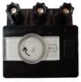
The determination of the order of phases is usually carried out by a phase indicator of an induction system of type I517M, which is an asynchronous squirrel-cage motor, the rotation of which, when connected to the terminals of the mains with a normal phase of rotation, occurs in the direction of the arrow indicated on it or against — with the opposite phase of rotation.
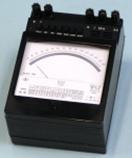
 Phase sequence and phase shift angles can be determined using one of the following devices: single-phase phase meter (for example, D578), VAF-85M phase indicator, single-phase wattmeter, electronic oscilloscope.
Remove vector charts
When taking vector diagrams, a symmetrical three-phase system of phase or line voltage vectors is usually used as «reference vectors» relative to which the current vectors are plotted. Therefore, at the first stage of the measurement, it is necessary to check the correctness of the alternation and symmetry of the phases, measure the values of the phase (line) voltages and apply the voltage vectors on an arbitrary scale on a diagram at an angle of 120 ° (for a symmetrical system) ; measure the load current, which for more accurate results should be at least 20-30% of the nominal.
When measuring with a single-phase phasor, the voltage coil clamp of the phasor, marked with an asterisk, is connected to phase A and the other to the neutral wire. The current winding of the phasor is connected in series with the load with a clamp marked with an asterisk — to the generator or the output of the current transformer (with a transformer switching circuit). After the angle is measured, it is subtracted from the vector UA and the current vector IA is constructed in the accepted scale. The current vectors IB and IC are similarly defined. In the case of using linear voltage vectors as reference, the phasometer is connected to linear voltages.
When measuring with a high-voltage ampere-phase speaker type VAF-85M, the linear voltage vector UAB is taken as the reference point.The measured angles are counted from the HAB vector clockwise with an inductive load and counterclockwise with a capacitive one. The angle is determined by the dial, by turning which the pointer of the indicator device is set to zero. The angle is set correctly if, when moving the dial, the arrow moves in the same direction as the dial, otherwise the angle will differ from the counted one by 180 °. The current is removed without breaking the circuit of the current conductor using a current collection attachment.
Vector diagram constructed using a single-phase phasor (a), a VAF-85M device (b) and a single-phase wattmeter (c)
Using a single-phase wattmeter
 When measured with a single-phase wattmeter, the current coil is connected in series and in accordance with the load in the circuit of phase A. The beginning of the voltage coil is connected in series to the phase voltages UA, UB and UC (the end of the neutral wire coil) and recorded the wattmeter readings.
If on the reference voltage vectors the measured powers are placed in the selected scale according to the inclusion of the voltage winding, taking into account their signs and the perpendiculars are restored from their ends, then the point of intersection of the latter will be the end of the phase vector A. Similarly way, the position of the current vectors of phases B and C is also determined.
Using an electronic oscilloscope
When measured with an electronic oscilloscope, the phase shift between current and voltage can be determined using a linear reading method by comparing the voltage curve on the oscilloscope screen and the current curve taken by a current sensor (eg, a shunt). By combining the lines of their sweeps when using a two-beam oscilloscope, or by synchronizing the reading of the reference voltage - when using a single-beam oscilloscope, you can calculate the value and sign of the phase angle. The shear angle found is plotted from the corresponding reference voltage and a current vector is constructed.