Current measurement without breaking the circuit under test
The ability to measure the current in a controlled circuit without interruption is of particular importance during commissioning involving a large number of different measurements. This eliminates a number of undesirable phenomena associated with the rupture of the tracked circuit under load and errors in the recovery of the tracked circuit after the corresponding measurements. To measure the current without breaking the controlled circuit, indirect methods and special devices are used.
When determining the current in the monitored circuit without interrupting, the method of measuring the voltage of the well-known resistor R1 included in this circuit is widely used. For example, the current in the anode circuit of the vacuum tube YL is determined by the voltage drop Uk across the resistor R1 in the cathode circuit of this lamp (bias resistance): Ia = Uk / R1.
If R1 = 800 Ohm and the voltmeter shows a voltage Uk = 2 V, then the anode current Ia = 2: 800 = 0.0025 A. Measuring the voltage of such a resistor (800 Ohm) does not present any difficulties.
Schematic for measuring the current of the anode circuit of the vacuum tube
Using the same method, determine the current flowing through the aluminum busbar whose cross section is q = 100×10 = 1000 mm2 or 1×10⁻³ m2. The resistance of a section of tire of length l can be determined by the formula r = rl / q. Resistance of aluminum r = 0.03×10⁻⁶ Ohm
By measuring the voltage drop across the specified section of the bus, it is easy to determine the current flowing through it. For example, if the voltage across a 1 m section of bus is 0.003 V, the resistance of 1 m of bus of said section is 0.00003 Ohm, and the current flowing through this bus is 100 A.
It is common to measure the voltage drop at the outputs of current transformers when checking secondary circuits under load. Usually, the resistance (total) of the current circuits is known, therefore by measuring the voltage drop, the current in these circuits can be determined and also ensure that they are in good working order.
The electrical industry produces a number of devices that allow meters to be introduced into controlled circuits without compromising their integrity. These include test clamps and blocks, clamps, etc.
Using test clamps
The test clamp consists of two metal plates 2 and 6, contact screws (1 and 7 — for connecting the tested circuits, 3 and 5 — for connecting measuring devices and 4 — closing plates 2 and 6). If it is necessary to include ammeter PA4 in the controlled circuit, it is first connected to plates 2 and 6 with screws 3 and 5, and then screw 4 is unscrewed.
The circuit will not break when the ammeter is connected (before connecting it is closed with contact screw 4, after connecting the ammeter winding forms an additional circuit parallel to contact screw 4, and when it turns out, the current is not interrupted, but passes through the coil of the ammeter).
After measuring the current in the specified circuit, screw the contact screw 4, thereby removing the ammeter coil. If the ammeter is then switched off, the current is not interrupted as it can pass through screw 4.
Test clamp (a) and connecting an ammeter to it (b)
Test units are usually mounted on panels with relay protection and automation to supply circuits from measuring current transformers to the relevant devices.
Each test block consists of a base 4 with main contacts 2 and 7, preliminary contacts 3 and a short-circuit breaker 1, a cover 6 with a contact plate 5 and a test plug 12 with contacts 8 and 9 and terminals 10 and 11 for connecting measuring devices .
It is easy to ensure that the controlled circuit in the area between the contact screws of the test block remains closed both when the cover and control plug are inserted and when they are interchanged. With cover 6 in place, current can flow from the contact screw through the main contact 2 on the base 4, the contact plate 5 on the cover 6, the main contact 7 from the base 4 to the contact screw. When the cover 6 is removed, the current can flow from the contact screw through the main contact 2 of the base 4, the short circuit 1, the main contact 7 to the contact screw.
Test block: a — with cover, b — with test plug
If at some point, when pulling the lid, the current circuit through the contact plate 5 of the lid is interrupted and a current circuit is not yet formed through the short-circuit switch 1 on the base, the current can flow through a circuit from the contact screw through the preliminary contacts 3 of the base and contact plate 5 of the cover to the contact screw ... When the test plug is inserted with an ammeter connected, the current will flow from the test screw through the main contact 2 of the base 4, contact 9 of the test plug 12, ammeter PA, contact 8 of the test plug , main contact 7 from base 4 to control screw.
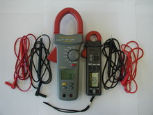
Using an electric clamp meter
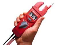 The scobometer consists of a current transformer with a split magnetic core, equipped with handles and an ammeter. To measure the current flowing through the wire, the magnetic circuit is propagated, covers the wire and then removed until the two parts of the magnetic circuit are closed. The current-carrying conductor in this case is also the primary winding of the current transformer.
The industry produces several varieties of electrical clamps for measurements in circuits with a voltage of up to 10 kV and up to 600 V. For current measurement in circuits with a voltage of up to 10 kV, the clamps KE-44 with measurement ranges of 25, 50, 100 , 250 and 500 A , as well as Ts90 with measuring ranges of 15, 30, 75, 300 and 600 A. In these clamps, the handles are reliably isolated from the magnetic circuit.
 To measure the current in a circuit with a voltage of up to 600 V, clamps Ts30 with measurement ranges of 10, 25, 100, 250, 500 A are used, which can also measure the voltage of two limits — up to 300 and 600 V.In addition, they produce electrical clamps included in a set for other measuring devices and devices, for example, for the VAF-85 voltammetric phase meter, which allow measuring the current in electrical circuits without breaking in the measurement range 1-5 and 10 A.