Finding faults in electrical circuits when testing them under voltage
Checking the electrical circuits under voltage is carried out only after checking their correct installation, only after checking the operation of the devices of these circuits without voltage and checking the insulation resistance of the circuits, after checking the reliability of all clamps in the circuits by shaking hands and screwdriver. The circuits are checked with the supply circuit voltage removed so that the electrical receivers do not turn on.
First supply of voltage to the electrical circuit
When voltage is first applied to the circuit, the fuse in the circuit's power supply circuit may blow or the circuit breaker may trip due to a box short. In this case, it is necessary to find the location of the short circuit when the circuit is disconnected from the network. This can be done by re-measuring the insulation resistance of the circuit to the case at different points in the circuit, disconnecting parts of the circuit if necessary.
After powering up the electrical circuit, the operation of all its devices is checked in all operating modes provided by the circuit.
Possible damage to the elements of the electrical circuit when checking them under voltage
When checking electrical circuits under voltage, malfunctions in the operation of individual elements of the circuit are possible. All these refusals can be reduced to several types:
1. Lack of contact where it should be, — malfunction of contacts in devices, weak contacts in terminals, damage to wires.
2. Having a contact where it should not be, — malfunction of the contacts in the device, short circuit between live parts, short circuit to the body of live parts of the equipment.
3. Current bypass (bypass) — for example, a case breakdown button post past the button. This causes the device to turn on, which may be due to moisture and conductive dust.
4. Mismatch with the circuit of some devices and its parts, for example, the winding of the device for a different voltage than the voltage in the control circuit. All these malfunctions can appear periodically, which makes it difficult to find them. The tuning methods in such cases depend on the characteristics of the circuit.
How to find faults in an electrical circuit
Let's look, for example, at a part of the electrical control circuit, on which we will trace the troubleshooting in the event of a malfunction of the KM3 starter.
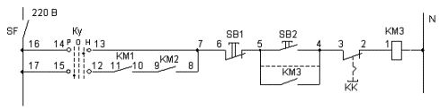
Let's say the KM3 doesn't turn on. After that, it is necessary to recheck the inclusion of the SF machine in the control circuit. When you turn it on, you need to check the presence of voltage at the output of the machine with an indicator.
The KU key must be placed in position H — regulation, because in this position the KM3 starter can be switched on independently of the others.
If the starter does not turn on when you press the Start button, then you need to check the voltage at pin 1 of the coil, you can check the indicator.
There is tension. In this case, it is necessary to check the integrity of a suitable neutral wire by checking the voltage with a bipolar indicator between points N and 1.
 There is tension. After that, you need to check the tightness of the clamps of the starter coil or touch the contacts, if necessary, remove it, clean the clamps from oxides, check the integrity of the coil winding. Then the working coil should work.
There is no voltage on the coil when it is determined when determining with a bipolar indicator, the unipolar indicator shows the voltage at point 1. In this case, you should check the integrity of the neutral wire suitable for the coil, the approach of the neutral wire to the entire control circuit to check the voltage from the indicator of the exit from the SF machine to the housing.
There is no voltage at point 1. Check voltage at point 2. If present, check terminals and wire integrity 1 — 2.
There is no stress in point 2. Check the voltage in point 3. If so, check the contacts of the KK relay, the terminals of the KK relay.
There is no stress in point 3. Check the voltage at point 4, and if there is, check the integrity of wire 3 — 4, its clamps.
There is no stress at point 4. Check the contacts and terminals of the Start button and if there is no voltage, check further to the SF machine.
All checks to the «Start» button from the starter coil must be carried out with the «Start» button pressed or connecting a wire parallel to it (dotted line in the figure).
After troubleshooting in the position of the switch H — adjustment, you can try to turn on the starter in the position P — work. In this case, the dependence of the inclusion of the starter KM3 on the inclusion of the starters KM1 and KM2 is introduced, therefore, when checking, they must be included.
If the KM3 does not turn on, then you should check in the same way from point 7 to point 17 (7 — 8 — 9 — 10 — 11 — 12 — 15 — 17).