How to measure AC current and voltage
Measurement alternating current and voltage can be produced directly by measuring devices of any principle of operation except magnetoelectric. Magnetoelectric devices can be used after converting AC to DC.
Devices with different operating principles have their advantages and disadvantages, different frequency and temperature ranges, different sensitivity to disturbances and mechanical influences, etc. Knowledge of these parameters is necessary for the correct selection of a measuring device.
To extend the limits of AC voltage measurement, instead of active additional resistances, capacitive ones are sometimes used.
 The measured voltage U creates in capacitor current I = jwCU, which can be measured with an ammeter of the electromagnetic system. However, in the presence of higher harmonics, the direct proportionality between current and voltage is violated, therefore, instead of an additional capacitor, a capacitive divider is preferred and the measurement is carried out with an electrostatic, lamp or digital voltmeter.
When directly switching on the measuring device, the same requirements must be observed as when DC current and voltage measurement.
Current and voltage measuring transformers are often used to measure large alternating currents and voltages. Voltage transformers are connected in parallel with the measured circuit and operate in a near-no-load mode, current transformers are connected in series with the measuring circuit and operate in a near-short-circuit mode.[/banner_dop
 When measuring with current and voltage transformers, the following requirements must be met:
1) the rated voltage of the primary winding of the current (voltage) transformer must be at least the voltage in the measured circuit;
2) the nominal current Ia (voltage Un) of the measuring device must be not less than the nominal current I2n (voltage U2n) of the secondary winding of the transformer; they usually match.
Device conversion factor:

where I1n (U1n) is the rated current (voltage) of the primary winding of the current (voltage) transformer; k is the coefficient of the scheme; N is the maximum scale reading of the instrument. For cases Ia = I2n or Uc = U2n.
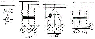
The values of the circuit coefficient for various schemes of connection of meters to voltage transformers are shown in the figure.
 3) the rated load of the transformer in the accepted accuracy class must be not less than the load connected to the transformer.The nominal load resistance, the largest for a current transformer and the smallest for a voltage transformer, are specified in the passport for the transformer and determine the resistance that can be included in the secondary winding of the transformer without increasing the error above a permissible such.
4) when working with phase-sensitive devices, it is necessary to observe the order of inclusion of the windings of the transformer. Changing the order leads to a rotation of the corresponding vector by 180 °.
