Adjustment and repair of magnetic amplifiers
A magnetic amplifier is an electrical device that uses controlled inductive resistance to amplify an input signal.
The commissioning program for magnetic amplifiers is varied and depends on the requirements for the drives in which the magnetic amplifiers are installed. Usually this is an external examination, checking the dielectric strength of the windings, measuring the resistance of the windings to direct current, checking the polarity of the windings, determining the ratio of the number of turns of the windings, checking the operation of the amplifier in the nominal mode and in the mode of maximum workloads.
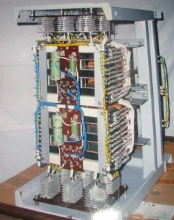
During an external inspection of the magnetic amplifier, attention is paid to the quality of the lamination of the magnetic cores, the size of the air gaps, the reliability of the bolted connections securing the magnetic cores, the integrity of the coils, solid rectifiers, and transformers included in the power supply of the magnetic amplifier are checked .Cores of magnetic amplifiers made of special alloys (for example, permaloid) change the magnetic permeability to a large extent during shaking and shocks, so they must be checked carefully.
The insulation of the windings of the magnetic amplifier is tested together with the secondary switching circuits with a megometer 500 or 1000 V. The value of the insulation resistance is not standardized separately, except in specially provided cases. Along with other secondary circuits, it should be at least 0.5 megohms.
Since there are no moving parts in the magnetic amplifier, it is considered a reliable element of the automatic control system. However, during operation, various malfunctions are possible, mainly related to mechanical damage to the windings of magnetic circuits or elements of power supplies.
The main malfunctions of electric drives with magnetic amplifiers:
1. The speed of the electric motor changes periodically
The possible reasons for this are for the driven PMU and PMU-M: 1) the current connection is incorrectly adjusted, 2) a short circuit to the control circuit housing (control setting potentiometer slider, etc.), 3) periodic switching of the load (rotating shock load).
For PMU-P drives: 1) open loop with flexible feedback, 2) large backlash in the connection of the shafts of the electric motor and the tachogenerator.
2. Poor mechanical strength. Causes — current feedback is incorrectly set or the reference potentiometer is incorrectly connected.
3. The motor rotates at a frequency higher than the maximum. Most likely, the reason for this is an open circuit of the excitation.The motor will also run at a frequency higher than maximum speed if the ends are reversed on the motor terminal block when connected.
4. The speed is not regulated (speed is low). The motor is adjustable (low speed only) but has no rated speed or minimum speed.
In most cases this is due to an open circuit in the control circuit. Understanding, of course, must be found and remedied. An open circuit in the reference potentiometer circuit is also possible.