Load break switches: purpose, device, principle of operation
 A load-break switch is a three-pole alternating current switching device for voltages above 1 kV, designed to interrupt the operating current and equipped with a drive for manual or automatic control.
Load-break switches are not designed to break short-circuit current, but their capacity corresponds to electrodynamic short-circuit resistance. In 6-10 kV distribution networks, circuit breakers are often called circuit breakers with a breaking capacity of less than 20 kA.
 The design of a vacuum load switch with a magnetic latch 1 release spring, 8 — top cover, 9 — coil, 10 — ring magnet, 11 — armature, 12 — armature sleeve, 13 — cam, 14 — shaft, 15 — permanent magnet, 16 — reed switches (contacts for external auxiliary circuits)
 Load-break switches are used in the connections of power transformers on the high-voltage side (6-10 kV) instead of feeder switches, if possible according to the operating conditions of the electrical installation. Since they are not designed to interrupt the short-circuit current, the functions of automatically disconnecting the transformers in the event of a fault are assigned to fuses or to switches belonging to the previous connections of the system, for example, line switches located closer to the power source .
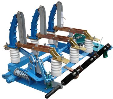
In distribution networks, the most common designs of load-break switches (VNR, VNA, VNB) with damping devices from generating gas.
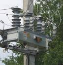
Gas generation type (BH) damping load-break switch a — general view of the switch; b — extinguishing chamber
As can be seen from the figure, three-pole disconnector elements are used here for internal mounting. On the supporting insulators of the disconnector there are fire extinguishing chambers 5. Auxiliary knives are attached to the disconnector blades 1 4. The drive of the disconnector is also changed to ensure the necessary speed of the blades when switching on and off, regardless of the operator. For this, springs 6 are provided, which are stretched when the disconnecting shaft 3 is rotated, and when they are released, they transfer their energy to the moving parts of the device.
In the "on" position, the auxiliary knives enter the damping chambers. The contacts of the disconnector 2 and the sliding contacts of the fire extinguishing chambers 7 are closed.Most of the current flows through the contacts of the disconnector 8 during the tripping process, the contacts of the disconnector first open; in this case, the current is shifted through the auxiliary blades 4 in the damping chambers. A little later, the contacts in the chamber open. Arcs are ignited, which are extinguished in the stream of gases — decomposition products of Plexiglas inserts 8.
In the "off" position, the auxiliary knives are outside the extinguishing chambers; at the same time sufficient insulation gaps are provided. The highest breaking current of the load switch type VN (active or inductive, but not capacitive) is 800 A at a nominal voltage of 6 kV and 400 A at a voltage of 10 kV, the nominal continuous currents are 2 times smaller and correspond to the operating currents of the disconnectors.
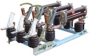
 VNR-10/630 load break switch