How to measure the winding resistance of a DC motor
 Measuring the winding resistance of a DC motor is a very important element for checking motors, as the measurement results assess the condition contact links coils (rations, bolted, welded joints).
Resistance measurement DC motor windings are manufactured by one of the following methods: ammeter-voltmeter, single or double bridge, and microohmmeter. It is necessary to remember about some characteristics of measuring the resistance of the windings of DC motors.
 1. The resistance of the series winding of the field, equalizing winding, winding of the additional poles of DC motors is small (thousandths of ohms), therefore measurements are made with a microohmmeter or a double bridge.
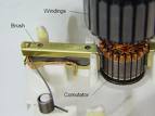
2. The resistance of the armature winding is measured by the ammeter-voltmeter method using a special two-contact probe with springs in the insulating handle.
Measuring the armature resistance of a DC motor using a two-pin probe
 The resistance measurement is carried out as follows: a direct current from a well-charged battery with a voltage of 4 — 6 V is supplied in series to the collector plates of the stationary armature with the brushes removed. Between the plates to which the current is applied, the voltage drop is measured using a millivoltmeter.
The required resistance value of one armature branch of a DC motor:

Similar measurements are made for all other engine manifold plates. The resistance values between each adjacent plate should not differ from each other by more than 10% of the nominal value (if the DC motor has an equalizing winding, the difference can reach 30%).
The measurement of the insulation resistance of the windings and the checking of the dielectric strength of the insulation of the windings of a DC motor are carried out as insulation resistance measurement induction motor windings.