How to check the correct connection of windings in asynchronous electric motors
Checking the correctness of the connections of the terminals of three-phase windings comes down to determining the beginning and end of each phase.
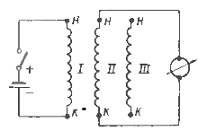
The beginning and end of the phases can be determined using a millivoltmeter. To do this, first, using a megohmmeter or a test lamp, determine the belonging of the winding terminals to individual phases. Then one of the phases is connected to the winding switch a DC source that is chosen so that a small current flows through the motor winding (a 2 V battery is desirable). To reduce the current in the circuit, turn on rheostat.
 Scheme for checking the correct connection of the terminals of the three-phase windings of the electric motor
The moment the switch is turned on or off, the windings of the other two phases will be induced electromotive force, and the direction of this electromotive force will depend on the polarity of the ends of the winding of the phase in which the battery is connected.
If the plus of the battery is connected to the conditional «start», and the minus is connected to the conditional «end», then when the switch is turned off on other phases, there will be a plus on the «beginning» and a minus on the «ends», which can be determine from the direction of deflection of the needle of the millivoltmeter connected in series to the output ends of the other two phases. When the current is turned on by a circuit breaker, the polarity of the other phases will be reversed as indicated.
In cases where the motor has three wires connected to the winding in a star or delta, the correct connection of the phases can be checked by supplying the two wires with reduced voltage alternating current and measuring the voltage between the third wire and each of the wires connected to the network with a voltmeter.
When properly connected, these voltages will be equal to half the voltage applied to the two pins, and this voltage ratio is maintained every two pins.
The experiment should be performed three times, applying voltage to a different pair of terminals each time. If one of the phases is connected incorrectly, then in two experiments out of three, the voltages between the third terminal and each of the other two will be unequal.
This experiment in the case of squirrel-cage induction motor should be carried out at a voltage of 1/5 — 1/6 of the rated voltage to avoid overheating of the windings, in case of phase rotor, its coil must be open.

