How to measure the transformation ratio of current transformers
Measurement transformation coefficient current transformer manufactured to establish compliance with its passport and design data, as well as to set a given transformation ratio for transformers manufactured with a device that allows them to be replaced.
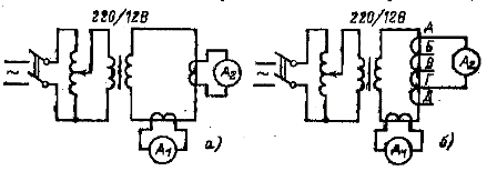
Measurement of the transformation ratios is made according to the diagram in fig. 1, and for reference and bushings transformers and according to the diagram in fig. 1, b — for built-in.

Rice. 1. Schemes for checking the transformation ratio of current transformers
The transformation ratio of current transformers is defined as the ratio of primary current to secondary: нtt = I1 / I2
For embedded current transformers, the transformation ratio is checked for all branches. In case the taps of the built-in current transformers do not have labeling or it is not clear enough, it should be checked and labeled based on the results of the intention of the turns ratio.
The largest transformation ratio should be between the terminal branches. It is easier to check the marking of the branch by measuring the distribution of branch voltages. For this purpose a voltage of about 100 V is applied to two branches and a Voltmeter measures the voltage between all the taps. Payment scheme voltage distribution is shown in fig. 2.
The maximum voltage corresponds to the final branches: A and D. After detecting branches, they are supplied with voltage and a voltmeter measures the voltage between branch A and others. The voltage will be distributed in proportion to the number of revolutions, that is, the transformation ratio.

After determining the taps, use a voltmeter to measure the current transformation ratio of all taps. When determining the voltage distribution over taps for current transformers with the same ratio in the first and last step (for example, in current transformers 600/5 the coefficients for the steps will be: A -B — 200/5; A -B — 300/5; A — G — 400/5; A-D — 600/5; G -D — 200/5) it is taken into account that the last stage has an additional number of turns to compensate for voltage losses in current transformers. In such transformers, the voltage is higher on the last stage G-D compared to the first, which is an additional check on the marking of the first A and last D branches.

Rice. 2. Scheme for determining the branches of built-in current transformers according to stress distribution
